
Chip multiprocessor with multiple operating systems

a multi-processor and operating system technology, applied in the field of computer chip architecture, can solve the problems of system b>100/b> and b>200/b> suffering from well known scalability problems, operating system does not scale well to may be unavailable or costly for locating a large number of processors, etc., to achieve the effect of reducing the inherent cabling problem, reducing the latency required for communication, and improving the efficiency of messag

Inactive Publication Date: 2005-03-29
SONRAI MEMORY LTD
View PDF11 Cites 13 Cited by
  • Summary
  • Abstract
  • Description
  • Claims
  • Application Information

AI Technical Summary

Benefits of technology

"The present invention provides a multiprocessing system with multiple processors mounted on a single die. These processors can execute one of multiple operating systems, reducing the cabling problem and latency between processors. This system also reduces chip-to-chip communication costs and increases power efficiency. Additionally, the invention increases scalability for multiprocessing."

Problems solved by technology

However, space may be unavailable or costly for locating a large number of processors necessary for maintaining a large compute density.
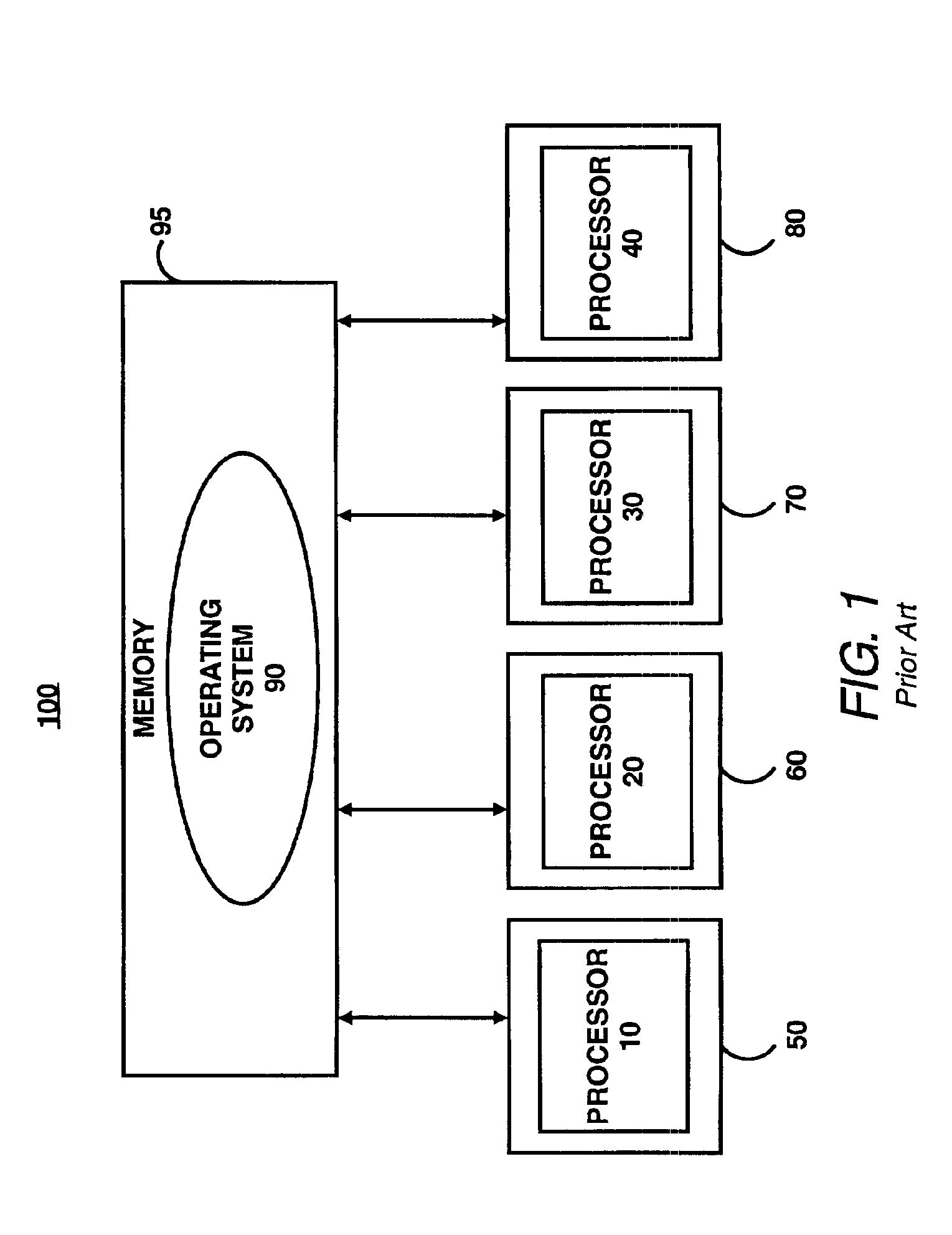
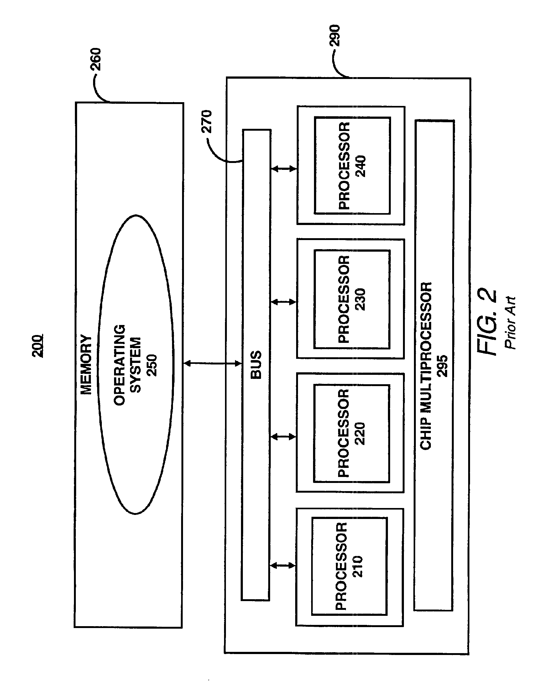
However, the systems 100 and 200 suffer from well known scalability problems.
A well known limitation of this scheme and other multiprocessing schemes utilizing a single operating system is that an operating system does not scale well to large numbers of processors.
For example, an operating system typically includes internal data structures that may be limited in the number of processors that can be supported, and limited bandwidth on a bus may slow transactions.
Thus, scaling becomes impractical above some small number (e.g., currently about four to at most 64 processors, depending on the operating system in question).
This architecture fails to provide multiple physical processors, implemented in hardware, on a single die.
Accordingly, this architecture suffers a performance penalty, because the single physical processor must task switch among multiple virtual processors (only one virtual processor can be running on the physical processor at any given time).
Moreover, if this architecture were to support multiple physical processors, it would need space for providing multiple dies, and processing speed would consequently be sacrificed due to the input / output procedures needed to communicate among the multiple separate processors and the memory.

Method used


Image

  • Chip multiprocessor with multiple operating systems
  • Chip multiprocessor with multiple operating systems
  • Chip multiprocessor with multiple operating systems

Examples


Embodiment Construction

In the following detailed description, numerous specific details are set forth in order to provide a thorough understanding of the present invention. However, it will be apparent to one of ordinary skill in the art that these specific details need not be used to practice the present invention. In other instances, well known structures, interfaces, and processes have not been shown in detail in order not to unnecessarily obscure the present invention.

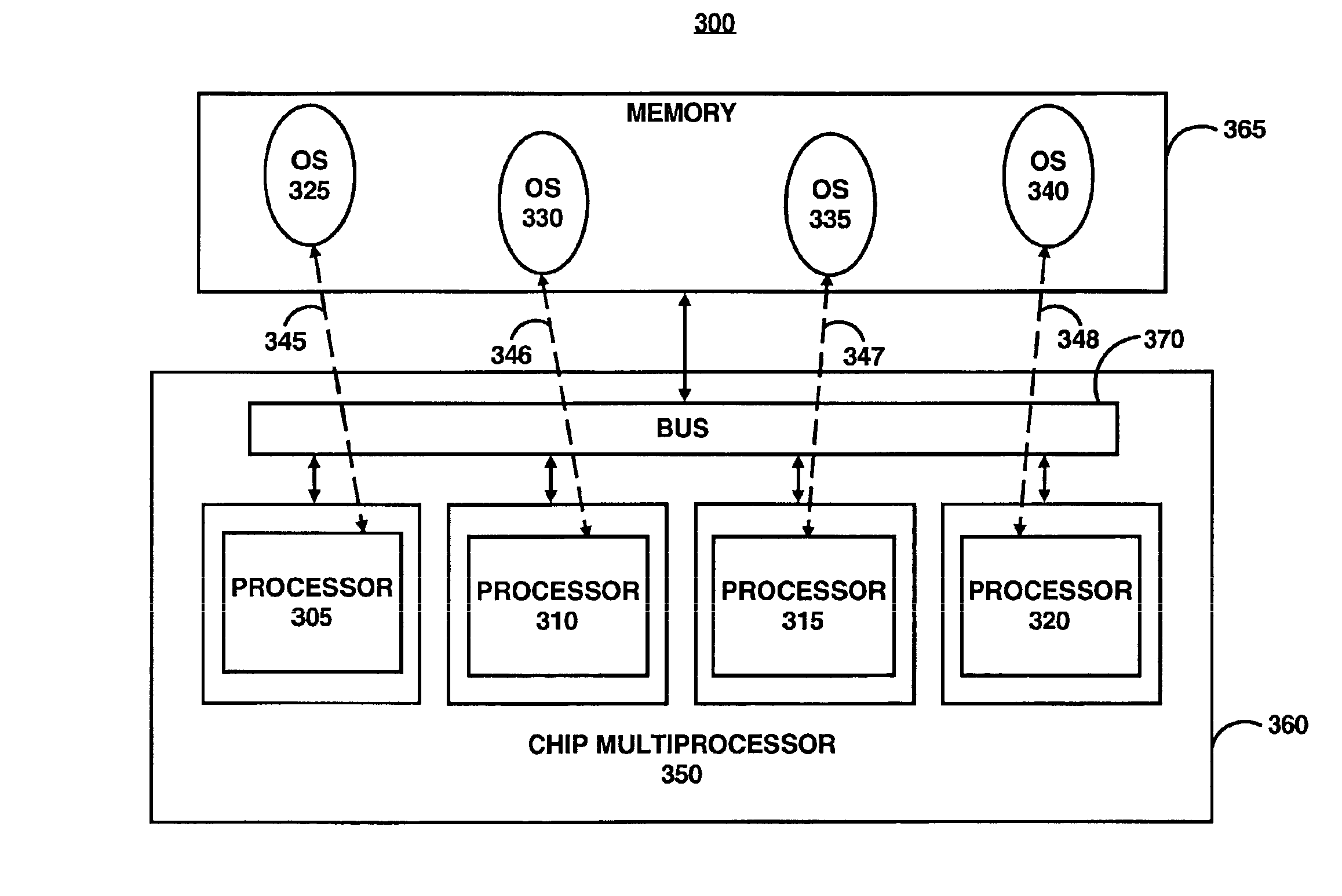
FIG. 3 illustrates an embodiment including a computer system 300 employing the principles of the present invention. System 300 includes a chip multiprocessor 350 having multiple processors 305-320 mounted on a single die 360. The processors 305-320 function with operating systems 325-340 respectively, as illustrated by connections 345-348. The operating systems 325-340 are stored in a memory 365. During operation, each processor 305-320 may access a respective operating system 325-340 by communicating with the memory 365, for example, vi...


PUM


Abstract

Multiple processors are mounted on a single die. The die is connected to a memory storing multiple operating systems or images of multiple operating systems. Each of the processors or a group of one or more of the processors is operable to execute a distinct one of the multiple operating systems. Therefore, resources for a single operating system may be dedicated to one processor or a group of processors. Consequently, a large number of processors mounted on a single die can operate efficiently.

Description

FIELD OF THE INVENTIONThe present invention is generally related to a computer chip architecture having multiple processors on a single die. More particularly, the present invention is related to a multiprocessing chip utilizing multiple operating systems.BACKGROUND OF THE INVENTIONExisting internet data centers (IDCs) pack hundreds of processors (e.g., servers and the like) in a single building for processing a large volume of data transactions. Generally, the compute density or number of nodes per volume defines the efficiency of the IDC. The compute density effects the amortization of the high cost of the IDC infrastructure (e.g., networking, power, cooling, maintenance, reliability, and availability support). Typically, the greater the compute density, the better the IDC will be able to amortize the high cost of IDC infrastructure. Accordingly, a large compute density may be preferred. However, space may be unavailable or costly for locating a large number of processors necessar...

Claims


Application Information

Patent Timeline
Patent Type & Authority Patents(United States)
IPC IPC(8): G06F15/16G06F15/167G06F9/50
CPCG06F9/5077G06F15/167Y02B60/142Y02B60/167Y02D10/00
Inventor RICHARDSON, STEPHEN E.VONDRAN, GARYSIU, STUARTKELTCHER, PAULVENKATARAMAN, SHANKARVENKITAKRISHNAN, PADMANABHAKU, JOSEPH
Owner SONRAI MEMORY LTD
Learn More