Apparatus and method for separating particles from a cyclonic fluid flow

a technology of fluid flow and apparatus, applied in the direction of liquid separation agent, filter regeneration, dispersed particle filtration, etc., can solve the problems of localized turbulence, achieve the effect of improving efficiency, and reducing the reentrainment of separated materials

Inactive Publication Date: 2005-04-05
OMACHRON INTPROP
View PDF79 Cites 187 Cited by
  • Summary
  • Abstract
  • Description
  • Claims
  • Application Information

AI Technical Summary

Benefits of technology

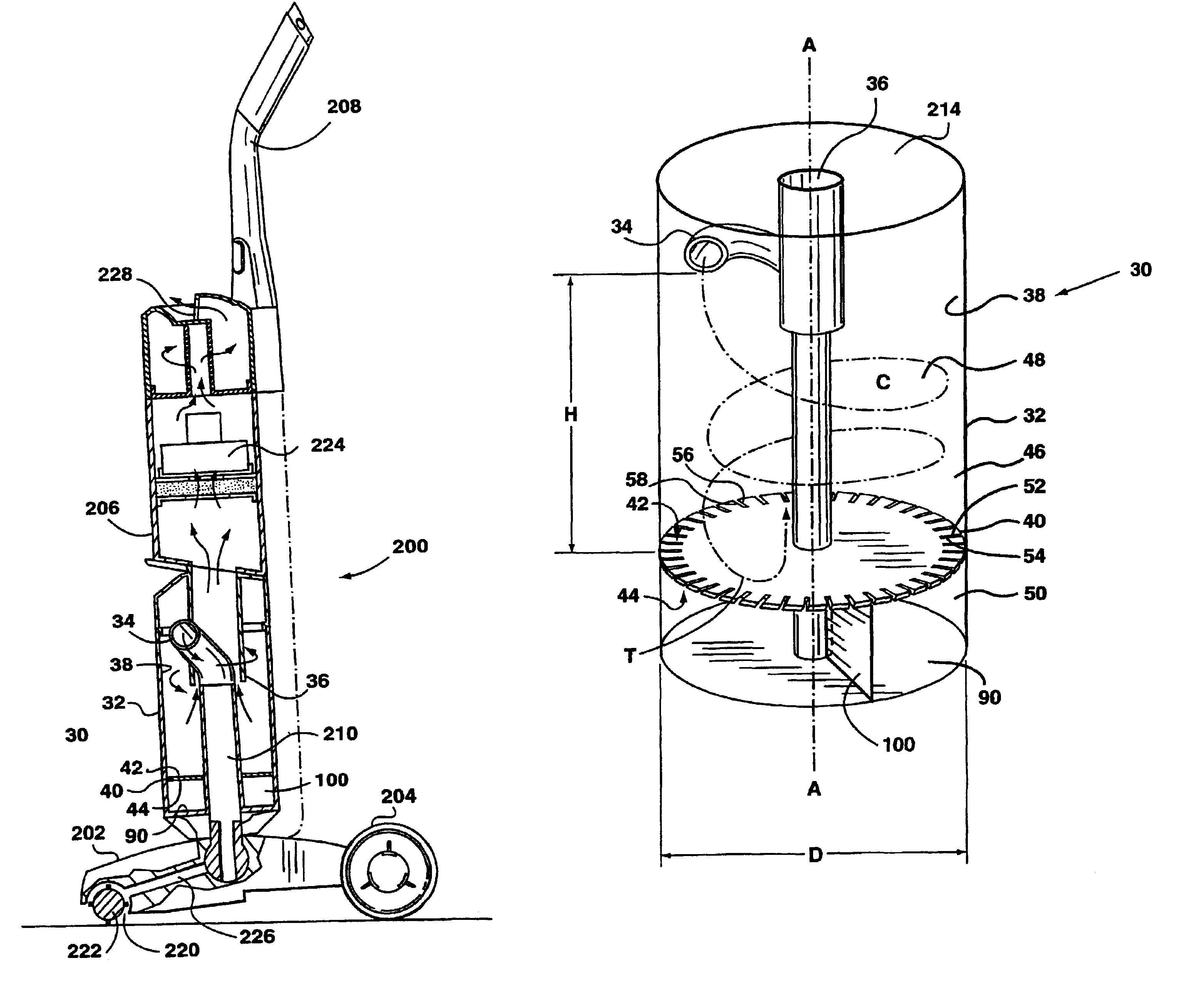
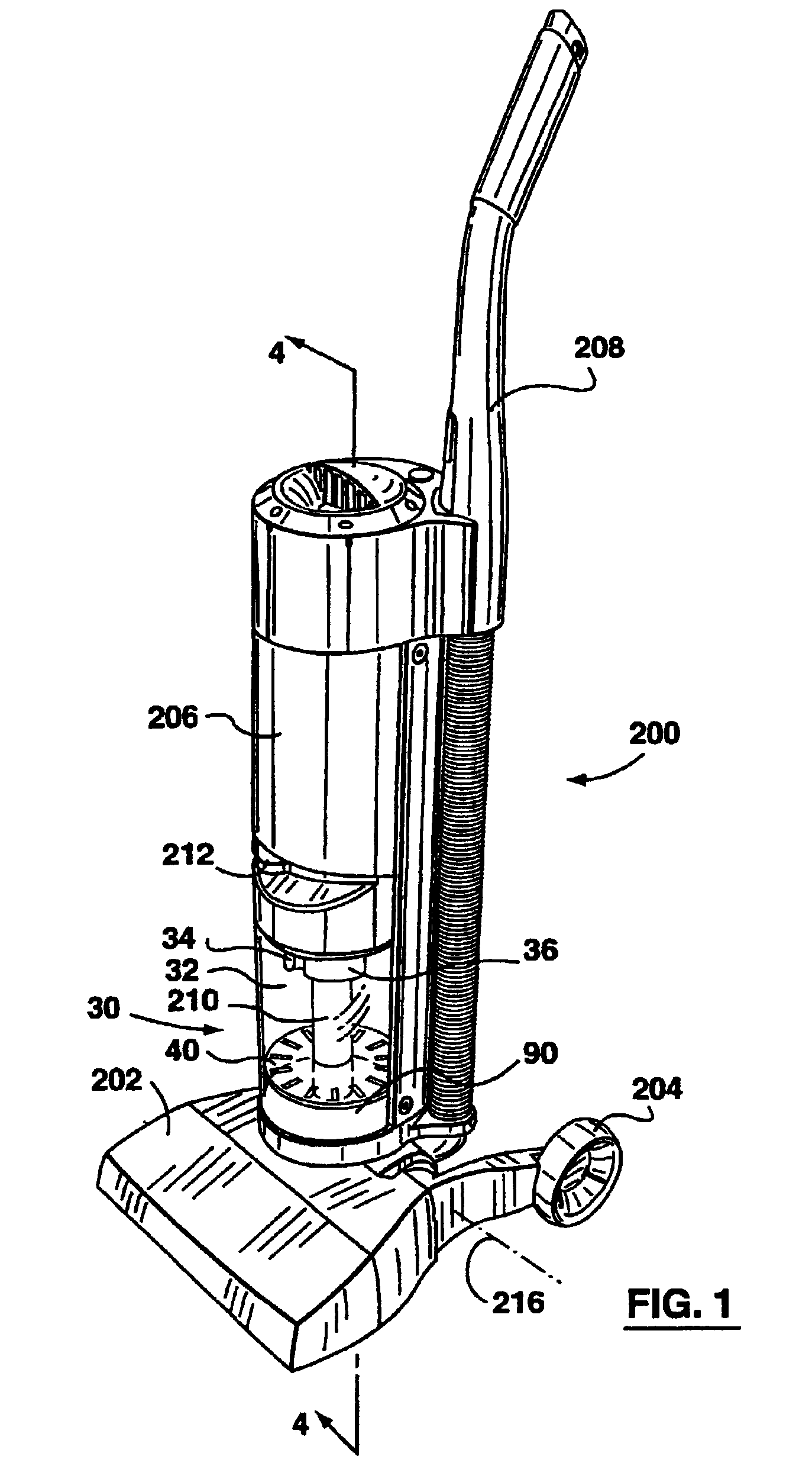
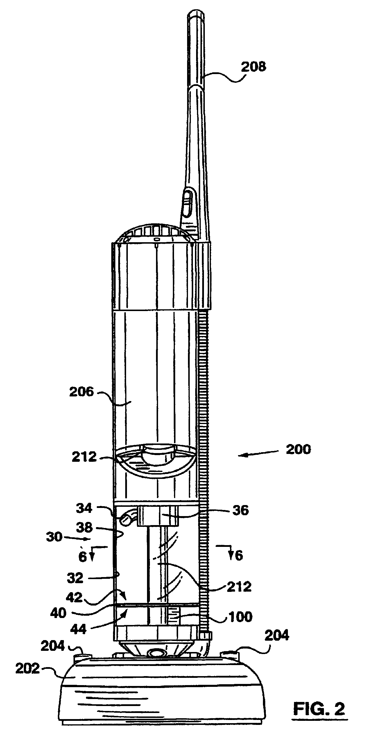
In has now been discovered that a single cyclone having improved efficiency (eg. up to 99.9% efficiency) may be manufactured by positioning in the cyclone chamber a particle separation member for creating a dead air space beneath the cyclonic flow region of the cyclone chamber wherein the dead air space is in communication with t...

Problems solved by technology

When the boundary layer breaks off from the upper surface, vortices are formed in the...

Method used


Image

  • Apparatus and method for separating particles from a cyclonic fluid flow
  • Apparatus and method for separating particles from a cyclonic fluid flow
  • Apparatus and method for separating particles from a cyclonic fluid flow

Examples


Embodiment Construction

The improvements in cyclonic separators described herein may be used with or in place of cyclonic separation devices of any sort which are used to separate particulate material from a fluid stream. For example, they may be used with a fluid stream consisting of one or more gasses such as industrial dust collection systems (eg. flue gas scrubbing), they may be used to classify particles according to their size or they may be used with a fluid stream consisting of one or more liquids (eg. a hydrocyclone) or with fluid streams comprising a gas / liquid mixture. It will be appreciated that they these cyclone separators may be used in any manner known in the particle separation art.

For example, the separation member according to the present invention may also be employed in the classification and / or sorting of particles by size. Particles to be sorted are entrained in a fluid flow and introduced to a cyclonic separator having a separation member according to the present invention, the sepa...


PUM

PropertyMeasurementUnit
Fractionaaaaaaaaaa
Fractionaaaaaaaaaa
Angleaaaaaaaaaa

Abstract

A particle separation member (40) is provided for use with a cyclone separator (30). The particle separation member (40) divides the separator (30) into a cyclone chamber (46) and a particle receiving chamber (50). The cyclone chamber (46) and the particle receiving chamber (50) communicating via a plurality of apertures (52) in the particle separation member (40).

Description

FIELD OF THE INVENTIONThe present invention relates generally to cyclonic separators. In one particular application, the invention relates to the cyclonic separation of particulate material from an air flow. In a preferred embodiment, the cyclonic separator is used in a vacuum cleaner to remove entrained particulate matter from an air stream.BACKGROUND OF THE INVENTIONThe use of a cyclone, or multiple cyclones connected in parallel or series, has long been known to be advantageous in the separation of particulate matter from a fluid stream. Typically, a relatively high speed fluid stream is introduced tangentially to a generally cylindrical or frusto-conical container, wherein the dirty air stream is accelerated around the inner periphery of the container. The centrifugal acceleration caused by the travel of the fluid in a cyclonic stream through the cyclone causes the particulate matter to be disentrained from the fluid flow and, eg., to collect at the bottom of the container. A fl...

Claims


Application Information

Patent Timeline
IPC IPC(8): A47L9/16A47L9/10B04C11/00B04C5/181B04C5/00B01D45/16B04C5/187
CPCA47L9/1608A47L9/165A47L9/1683B04C5/181B04C5/187B04C11/00B01D45/16Y10S55/03
Inventor CONRAD, WAYNE ERNESTPETERSEN, DAVE
Owner OMACHRON INTPROP
Why Eureka
Try Eureka