Method and apparatus for controlling motor drive type throttle valve

Inactive Publication Date: 2005-04-05
HITACHI LTD +1
View PDF7 Cites 23 Cited by
  • Summary
  • Abstract
  • Description
  • Claims
  • Application Information

AI Technical Summary

Benefits of technology

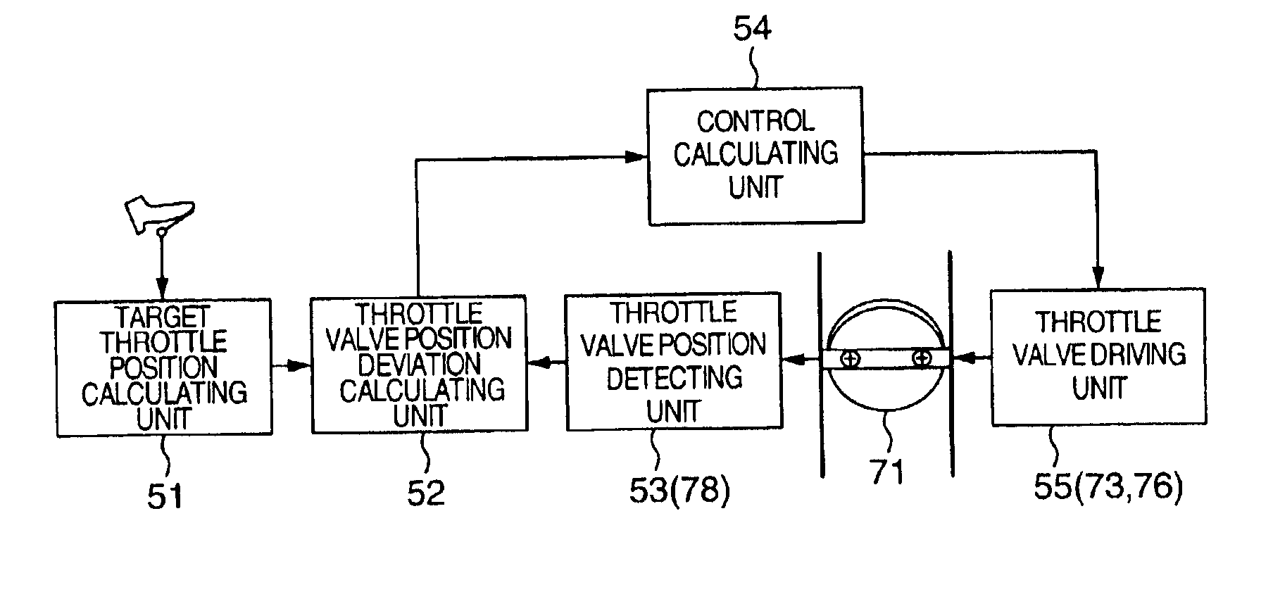
a control calculating unit for calculating a control signal for rotating or moving the throttle valve at predetermin

Problems solved by technology

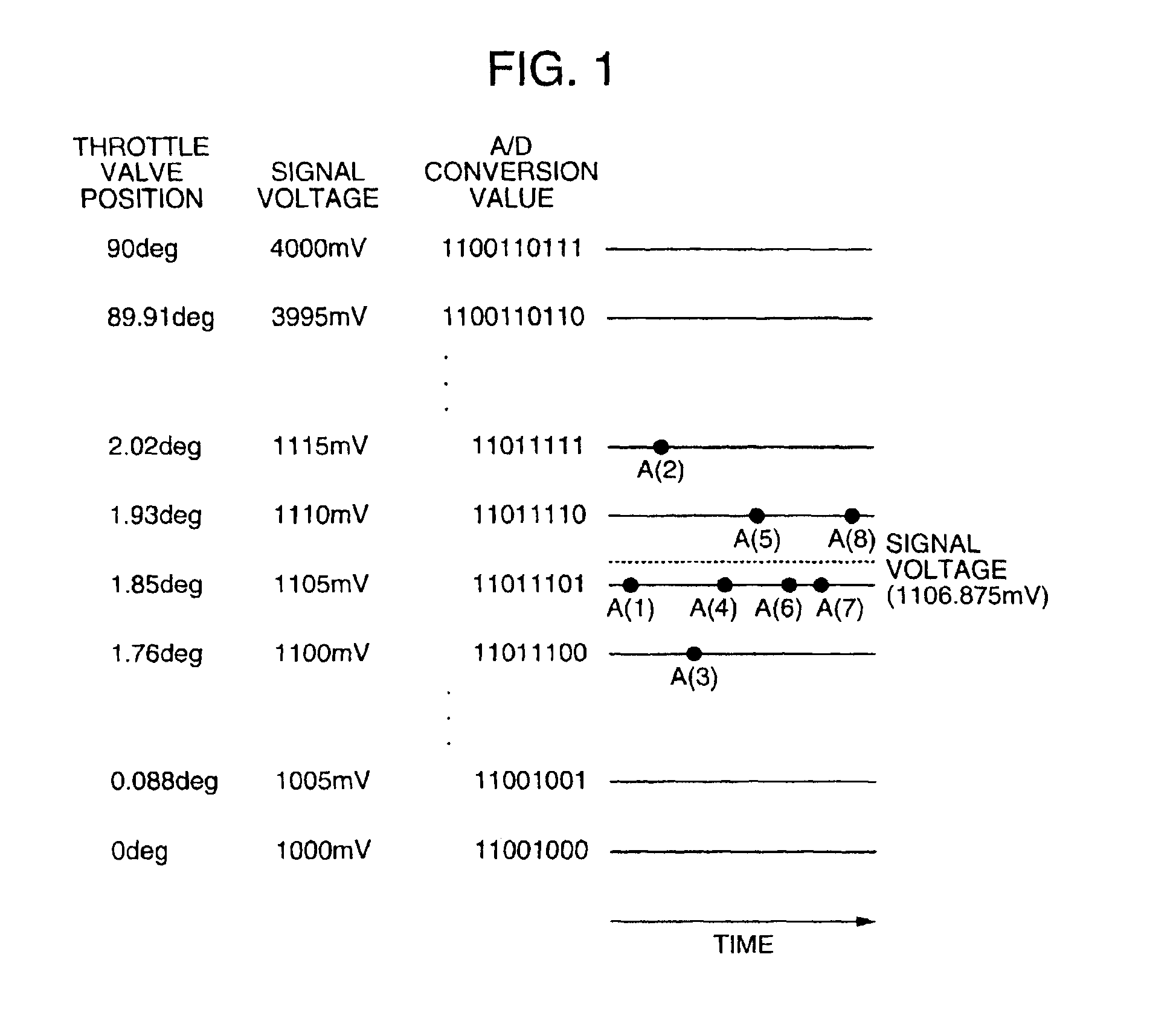
However, according to the above methods, it is not easy to allow a throttle valve to precisely trace a microstep of a target position.
It is, therefore, difficult to suppress the hunting accordin

Method used


Image

  • Method and apparatus for controlling motor drive type throttle valve
  • Method and apparatus for controlling motor drive type throttle valve
  • Method and apparatus for controlling motor drive type throttle valve

Examples


second embodiment

the invention shown in FIG. 6 will now be supplementally explained.

In the second embodiment, when the absolute value of the position deviation is equal to or less than the predetermined value, in order to prevent the hunting due to a dead zone such as friction or the like, it is also possible to construct in a manner such that the integration value setting unit stops the integration calculation in the integration value calculating unit, holds the integration value, and restarts the integration calculation when the absolute value of the position deviation exceeds the predetermined value.

Further, in the second embodiment, when the absolute value of the position deviation is equal to or less than the predetermined value and the target throttle position changes at a predetermined rate or more, or when the absolute value of the position deviation exceeds the predetermined value, the integration value can be also set to a predetermined value by the integration value setting unit. As a val...


PUM


Abstract

When the position of a throttle valve approaches a target value, an integration calculation of position control is stopped. When a deviation from the target value increases, the integration calculation is restarted. If an integration value includes no frictional amount, a motor output in which a motor and a spring are matched is set synchronously with a change in target value.

Description

BACKGROUND OF THE INVENTIONThe invention relates to a method and an apparatus for electronically controlling a throttle valve by a motor and, more particularly, to control method and apparatus of a throttle valve for feedback controlling a position of the throttle valve.In position control of an electronic controlled throttle, a technique for improving position resolution of a throttle valve has conventionally been used in order to control an idling rotational speed so as to become a constant speed. According to the position control, a position of the throttle valve detected by a sensor is converted into a digital value by an A / D converter constructed by a microcomputer, and a motor is controlled by software by using PID control or the like so that an opening degree of the throttle valve coincides with a target value on the basis of a difference (hereinafter, referred to as a deviation) between the actual position and the target position of the throttle valve.Therefore, if the user ...

Claims


Application Information

Patent Timeline
IPC IPC(8): F02D35/00F02D11/10F02D9/02F02D9/08F02D9/10F02D41/14F02D41/20
CPCF02D11/106F02D35/0007F02D9/10F02D2041/1422F02D2009/0284F02D2041/1409
Inventor HOSHINO, MASATOSHIICHIHASHI, TETSUYA
Owner HITACHI LTD
Why Eureka
Try Eureka