Vacuum packing machine with interior scale

a vacuum packing machine and scale technology, applied in the field of vacuum packing machines, can solve the problems of affecting the scale readout, the chamber itself has a tendency to distort, and the original design had several problems that have proven very difficult to overcome, so as to reduce the total weight range, eliminate the influence of the scale, and reduce the effect of weight error

Inactive Publication Date: 2005-04-05
DURANT WILL G
View PDF5 Cites 4 Cited by
  • Summary
  • Abstract
  • Description
  • Claims
  • Application Information

AI Technical Summary

Benefits of technology

In addition, the load cell supporting the scale is vented to atmosphere, thus eliminating any scale influence caused by a pressure differential between the inner workings of the load cell and the external load cell casing. This arrangement has been proven to reduce weight error between full vacuum and atmospheric pressure from two to three pounds to not more than 0.05 pounds. The machines can be fully automatic and do not require a machine operator to constantly adjust or manipulate the scale set points and cut-off points in an effort to get consistent package weights.
The arrangement also has several other advantages over the present technology. By removing the chamber itself from the weigh scale, a scale of much less total weight range may be utilized, thus improving the weight resolution of the scale. With the new arrangement, only one connection, that being the connection of the product supply tube to the filling spout, must be flexible. All other piping connections to the chamber may be rigid connections. Also, by removing the vacuum chamber itself from the weigh mechanism, there is no risk of weight error by an operator coming into physical contact with the external surface of the chamber during the filling process, thus causing weight inconsistency. Also, removing the vacuum chamber itself from the weigh mechanism enables the user to connect additional dust collecting and ventilation systems to the chamber doors without the risk of affecting the weight scale.
In addition, the new arrangement greatly simplifies the construction of the machine inasmuch as the vacuum casing can be directly bolted to the main framework of the machine without the need for external check rods, intermediate support frames and other chamber support devices previously used to isolate the chamber from the main framework of the machine.
The new arrangement thus makes it possible to fully automate the vacuum packer and maintain accurate weights.

Problems solved by technology

The original design had several problems that have proven very difficult to overcome.
In addition, the chamber itself has a tendency to distort when under vacuum.
This distortion greatly affects the scale readout.
This is especially true when using a single load-cell type of scale detection, as these devices are extremely sensitive to any distortion of the live load.
The difference in reading makes it extremely difficult to maintain consistent, accurate weights of the filled bags.

Method used


Image

  • Vacuum packing machine with interior scale
  • Vacuum packing machine with interior scale
  • Vacuum packing machine with interior scale

Examples


Embodiment Construction

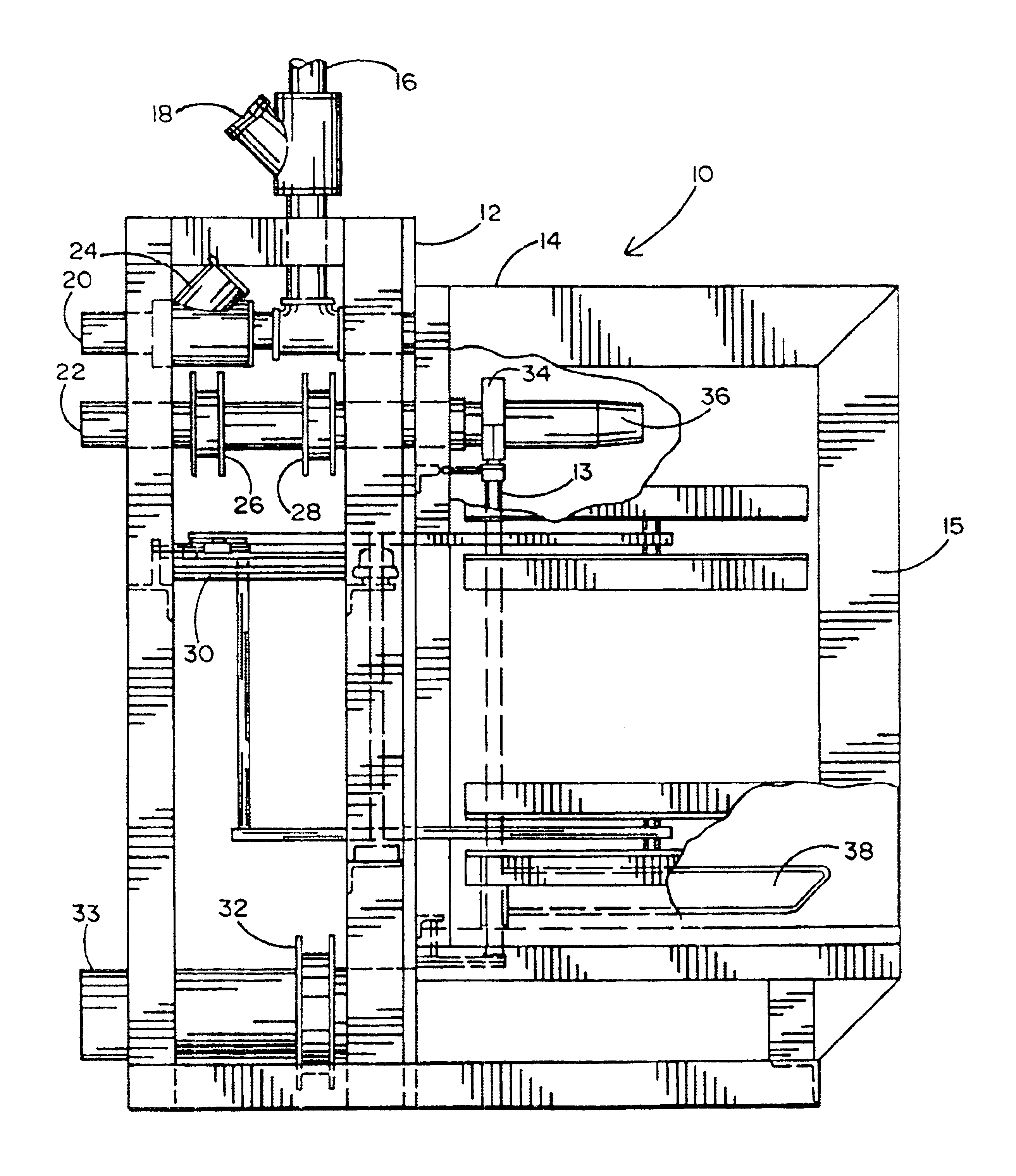
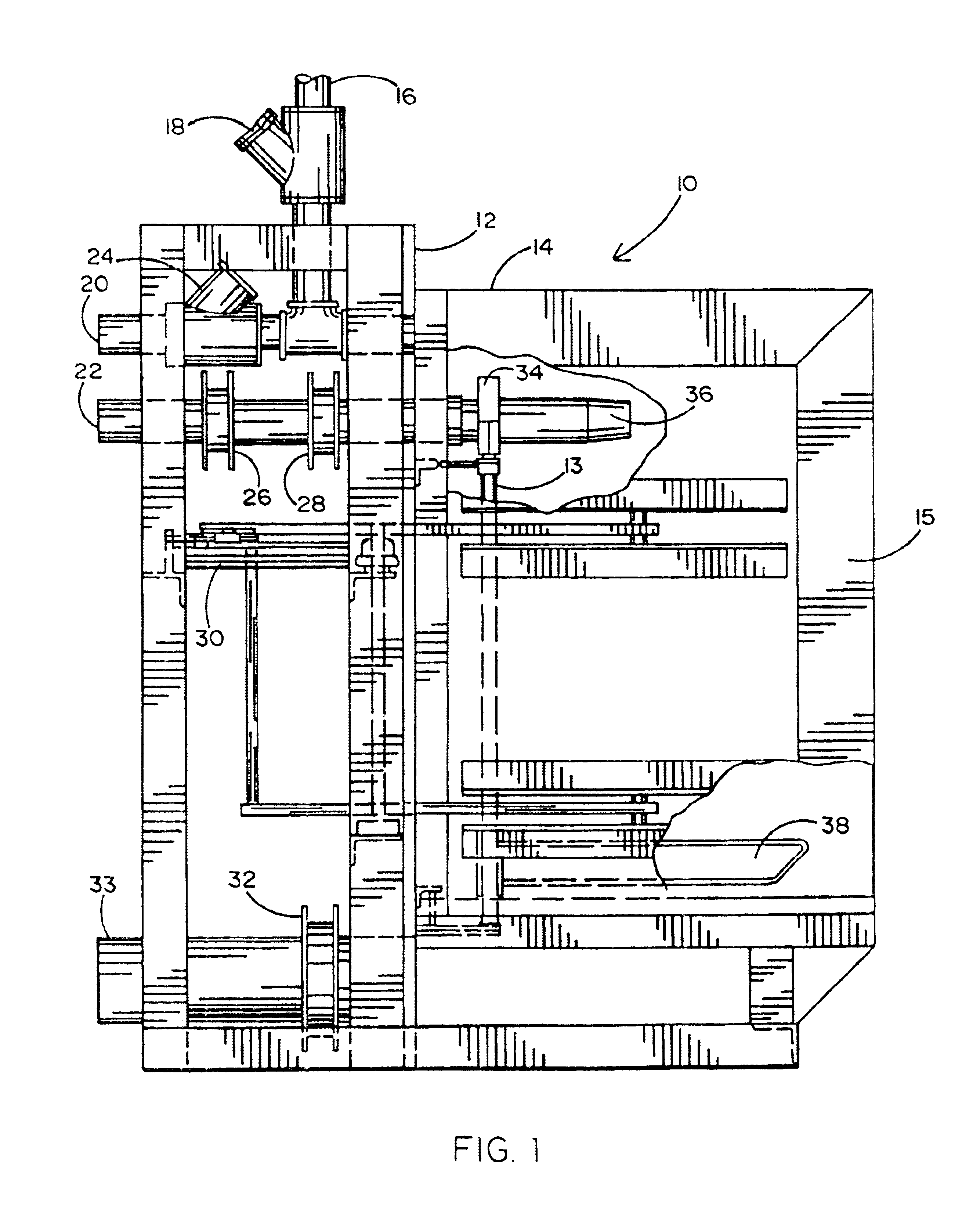
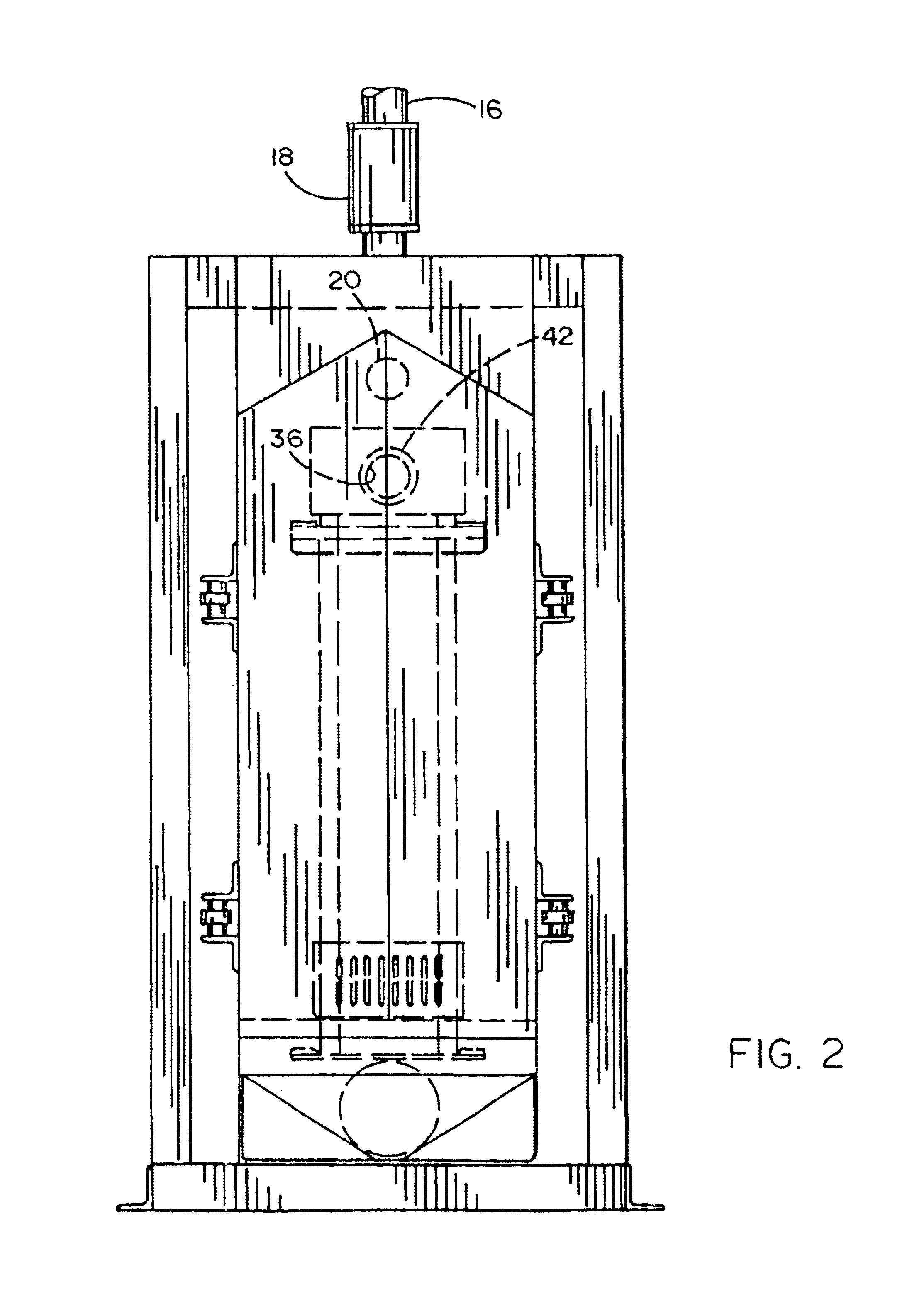
Referring to the accompanying drawings, it will be seen that a preferred embodiment 10 of a vacuum packer in accordance with the inventive features hereof is shown therein. More specifically, as seen for example in FIGS. 1 and 2, the packer 10 comprises a weighing section 13 and a chamber section 15 interconnected at a frame wall 12. The chamber section 15 comprises a vacuum line 16 and an atmosphere line valve 18 which are used to control air pressure reduction in the chamber section 15. Section 15 also provides a vent line 20 and a feed line 22. The vent line is used to selectively relieve the vacuum in the weighing chamber through a vent atmosphere valve 24. The feed line provides the particulate material to be packed into each bag. A pair of valves, namely, bulk butterfly valve 26 and trim butterfly valve 28, are employed to control flow in the feed line. Chamber 15 also provides a door opening and closing mechanism 30 and a dust collection vent line 33 controlled by a butterfly...


PUM

PropertyMeasurementUnit
weightaaaaaaaaaa
weightaaaaaaaaaa
weightaaaaaaaaaa

Abstract

A vacuum packer for filling valve bags employs a load cell-based scale mechanism located within the vacuum chamber. An interior packer front plate is supported from the back, inner wall of the chamber on four flexure spring check straps. The front plate is supported from a single load cell mounted on the back, interior wall of the vacuum chamber. Side bag retention plates, end retention plates and the lower bag support saddle are mounted to the packer front plate. A flexible connection is furnished between the back of the filling spout and the interior back wall of the vacuum chamber. All other required piping is made directly to the back wall of the chamber, thus removing them from the scale mechanism entirely.

Description

BACKGROUND OF THE INVENTION1. Field of the InventionThe present invention relates generally to packing machines which employ a vacuum to pack low density powder materials into valve bags and provide an accurate amount of such material based on the weight of the filled bag.2. Background ArtThe original vacuum packer designed especially for packing light density powders into valve bags was invented in the late 1950's by Clarence Carter. That machine comprises a basic framework. This framework supports a weighing scale mechanism. Suspended from the weighing mechanism is a large vacuum chamber with an access door on one side of the chamber. This chamber is suspended from the scale mechanism and checked back to the frame with check rods to keep the chamber from swinging laterally and longitudinally.Mounted within the chamber and to the chamber is the bag filling spout, bag support chair, interior side panels, vacuum and atmosphere piping connections and a clean-out port. All of these dev...

Claims


Application Information

Patent Timeline
Patent Type & Authority Patents(United States)
IPC IPC(8): B65B1/30B65B1/46B65B1/04B65B1/18B65B31/02
CPCB65B1/18B65B31/024B65B1/46
Inventor DURANT, WILL G.
Owner DURANT WILL G
Why Eureka
Try Eureka