
System and method for energy management

a technology of energy management and system, applied in the field of system for energy management, can solve the problems of a number of limitations, the system's ability to provide an alert to indicate the problem is somewhat limited, and the ability to display historical or statistical information is typically limited, so as to reduce the number of redundant workers and equipmen

Inactive Publication Date: 2005-04-05
SIEMENS IND INC
View PDF14 Cites 149 Cited by
  • Summary
  • Abstract
  • Description
  • Claims
  • Application Information

AI Technical Summary

Benefits of technology

In yet another embodiment, the system further includes a remote server which collects energy management information from multiple energy management systems and allows the information from one or more energy managements sites to be accessed via the Internet. Thus, an authorized person can view recent and historic energy management information from a particular system from anywhere in the world where an Internet connection is available. A number of advantages are provided by such a system. For example: an offsite consultant can review historical and present energy usage information to make recommendations; a large number of buildings may be managed from a single location reducing redundant workforce and equipment; the information may be accessed by local utilities to aid in load planning; personnel can access energy management information while away from the facility to troubleshoot problems; etc.

Problems solved by technology

While such systems are presently in use, they suffer from a number of limitations.
In addition, while such systems may recognize a problem, the system's ability to provide an alert to indicate the problem is somewhat limited.
Furthermore, the ability to display historical or statistical information is typically limited to a single computer connected to the controller.

Method used


Image

  • System and method for energy management
  • System and method for energy management
  • System and method for energy management

Examples


Embodiment Construction

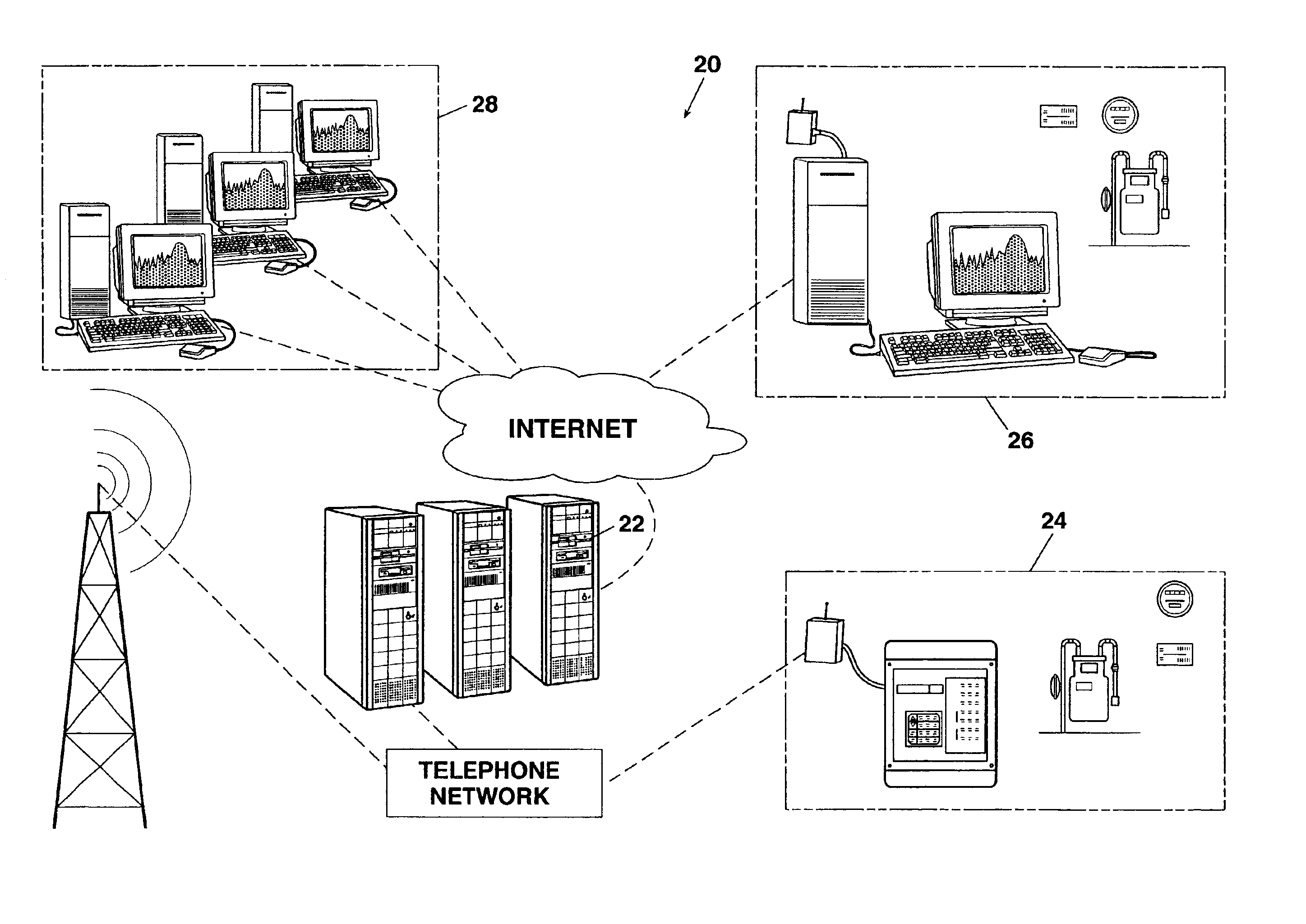
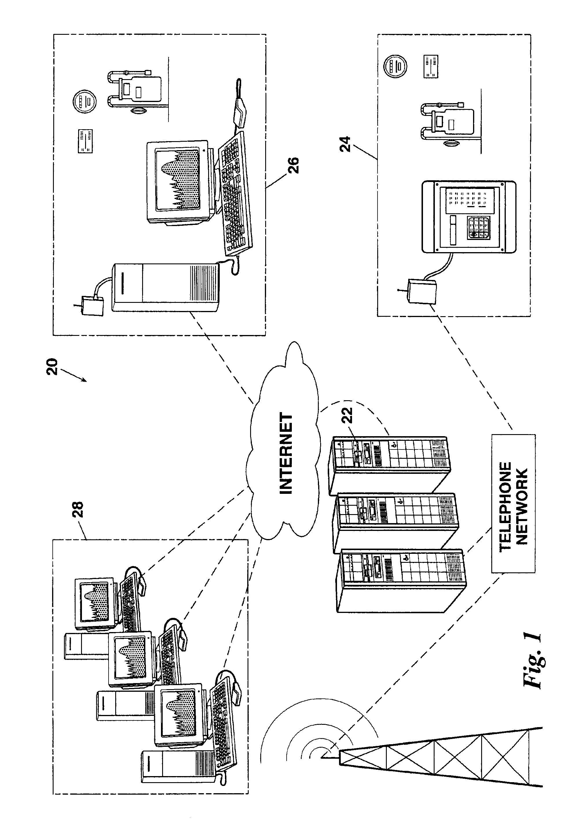
Depicted in FIG. 1 is a system for energy management 20 comprising: a server 22 for gathering and managing energy usage information from multiple sites; a first building automation system 24 communicating with the server 22 via a conventional telephone line; and a second building system 26 communicating with the server 22 via the Internet. The server Internet connection allows users 28 of the system 20 to remotely access information gathered by the server 22 as well as providing communication with individual building automation systems 26. In addition, the server 22 can monitor the information received from individual building automation systems 24 or 26 and, upon detecting an abnormal condition, access a paging system over a telephone connection to notify the appropriate personnel of a potential problem.

Referring to FIG. 2, server 22 is preferably a group of computers 30a-c which share a common database. In a typical server 22 individual computers 30a-c could be programmed to perfo...


PUM


Abstract

A building automation system having: a plurality of wireless remote devices, each wireless remote device including a wireless transceiver for transmitting and receiving digital information and an interface for energy management which can read a sensor, such as a temperature sensor, a flow sensor, an electronically readable gas or electric meter, or provide an output, such as a relay driver; and a controller having a wireless transceiver for digital communication with the wireless remote devices and a computer interface. Each wireless remote device includes an identifier to identify the type of interface present in the remote device and a serial number to allow the controller to communicate exclusively with any individual remote device. The controller interface allows the controller to communicate with a computer, and ultimately with a server to allow monitoring and control of the system from virtually anywhere in the world.

Description

BACKGROUND OF THE INVENTION1. Field of the InventionThe present invention relates to a system for energy management and a method for using the same. More particularly, but not by way of limitation, the present invention relates to a system which monitors a variety of conditions associated with energy usage in a building to provide management as well as monitoring such energy usage.2. Background of the InventionThe monitoring and management of energy usage in a building is generally of concern. There are a number of advantages to energy management, especially in large, commercial buildings. Obviously, intelligent management of heating and air conditioning systems can dramatically reduce the energy costs of operating such systems. Beyond that, however, an energy management system may provide an indication of problems in the building, provide meaningful forecasting of energy costs, reduce periodic maintenance, provide accurate usage information to the utility companies, among other thi...

Claims


Application Information

Patent Timeline
IPC IPC(8): G05D23/00
CPCH04L12/2818H04L12/2825H04L2012/2841H04W52/0261H04W8/26H04W24/00H04W52/0219H04W4/04Y02D30/70H04W4/38H04W4/33
Inventor HILDEBRAND, PAUL N.PARSONS, PHILIP L.
Owner SIEMENS IND INC
Learn More