Lightning arrester

a technology of arrester and light, which is applied in the installation of lighting conductors, connection to earth, relays, etc., can solve the problems of lowering the charge filling efficiency, difficult discharge, and inefficient formation of earth electric fields induced by thunderclouds at the uppermost part of buildings

Inactive Publication Date: 2005-04-05
LEE TECH KOREA CO LTD
View PDF5 Cites 22 Cited by
  • Summary
  • Abstract
  • Description
  • Claims
  • Application Information

AI Technical Summary

Benefits of technology

Accordingly, the present invention has been made in view of the above-mentioned problems, and it is an object of the present invention to provide a lightning arrester having a main electrode section formed at an upper portion of a fixing bar, into which earth charge is filled when a thundercloud approaches, a dielectric insulator formed at an outer portion of the fixing bar by using an electrification state of the fixing bar, an auxiliary electrode section having opposite electrodes, including conductive material, and integrally formed with the outer surface of the dielectric insulator, and TiO2 having high dielectric constant in relation to electrostatic capacity and capable enlarging a surface area of the auxiliary electrode section through filling a great amount of charge from an atmosphere into the auxiliary electrode section, thereby improving reliability of the lightning arrester, safely and previously seed-discharging ground charge of the main electrode and auxiliary electrode sections regardless of variation of charge contained in air, and safely discharging charge charged in the thundercloud into the earth even if the thundercloud is located far-remote from the earth.
The auxiliary electrode section includes a first auxiliary electrode member made of conductive material, formed at an upper surface thereof with a plurality of triangular plates arranged at a predetermined interval and formed at a center thereof with a first perforation hole for receiving the elongated column member of the upper polymer insulator, a pair of second auxiliary electrode members made of conductive material, making contact with an underside of the first auxiliary electrode member and formed at a center thereof with a second perforation hole for receiving the elongated column member of the upper polymer insulator, a third auxiliary electrode member made of conductive material and having a hollow column member receiving the elongated column member of the upper polymer insulator, and a filler. Upper and lower ends of the elongated column member extend beyond upper and lower ends of the hollow column member. The upper end of the hollow column member makes contact with an underside of the second auxiliary electrode members. A space is formed between an inner wall of the third auxiliary electrode member and an outer wall of the elongated column member when the elongated column member is received in the third auxiliary electrode member. The filler is filled in the space formed between the inner wall of the third auxiliary electrode member and the outer wall of the elongated column member in order to improve capacitance of the third auxiliary electrode member. O-rings are installed at upper and lower portions of the space in order to prevent the filler from being leaked.

Problems solved by technology

Therefore, the Franklin rod type lightning arrester cannot effectively deal with the lightning stroke caused by a thundercloud, which does not make the dielectric breakdown of air.
However, the lightning an ester disclosed in the above French Patent Laid-open Publication is installed at an uppermost part of a building to be protected so that an earth electric field induced by the thundercloud is inefficiently formed at the uppermost part of the building.
Thus, if discharge is induced through filling charge contained in air, filling efficiency of charge is lowered so that discharge is difficult.
In addition, the lightning arrester disclosed in the above Japanese Patent Laid-open Publication uses a plurality of electronic components so not only is a structure of the lightning arrester complicated, but also it frequently requires exchange and repair works for the components of the lightning arrester installed at the uppermost part of the building.

Method used


Image

  • Lightning arrester
  • Lightning arrester
  • Lightning arrester

Examples


Embodiment Construction

Hereinafter, a preferred embodiment of the present invention will be described with reference to the accompanying drawings. In the following description and drawings, the same reference numerals are used to designate the same or similar components, and so repetition of the description on the same or similar components will be omitted.

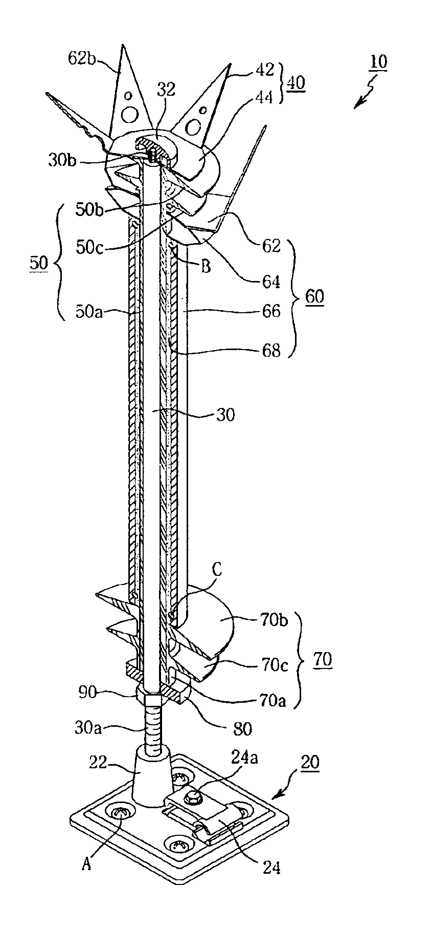
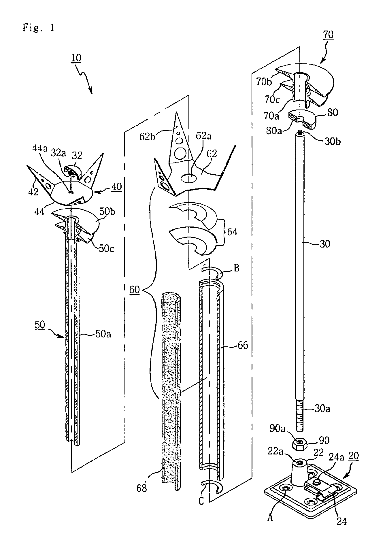
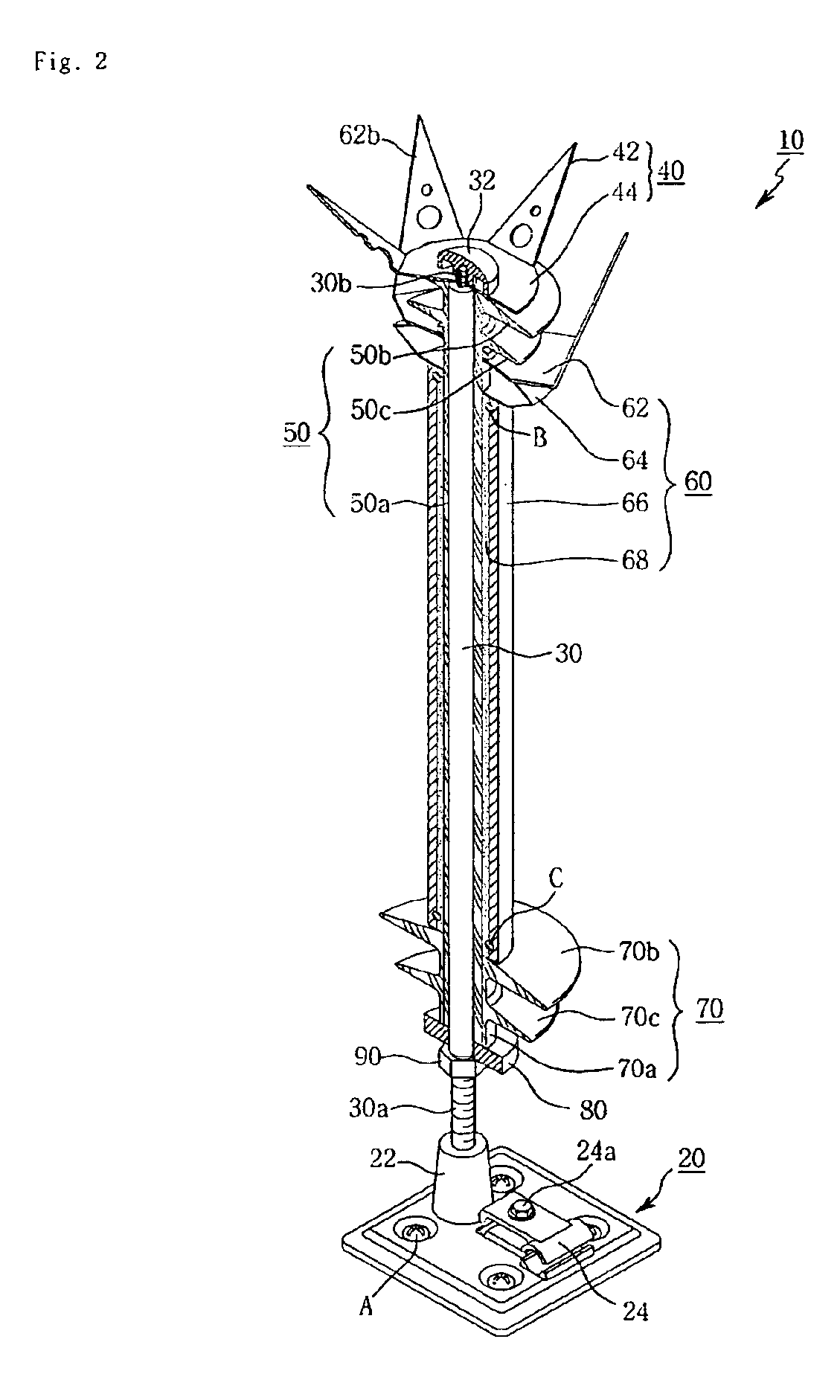
FIG. 1 is a partially sectional exploded perspective view of a lightning arrester 10 according to a first embodiment of the present invention, and FIG. 2 is a partially sectional perspective view of the lightning arrester 10 shown in FIG. 1.

As shown in FIGS. 1 and 2, the lightning arrester 10 of the present invention includes a fixing base 20 fixed to an uppermost part of an object to be protected through fixing screws A, a fixing bar 30 vertically installed on an upper surface of the fixing base 20, a main electrode section 40 made of conductive material and making contact with an upper portion of the fixing bar 30, an upper polymer insulator 50 having...


PUM


Abstract

Disclosed is a lightning arrester. The lightning arrester safely discharges earth charge of a main electrode section and an auxiliary electrode section regardless of a variation of charge contained in air, so charge charged in a thundercloud is safely discharged into the earth even if the thundercloud is located far-remote from the earth. The lightning arrester has a fixing base fixedly installed on an object to be protected by grounding a lightning circuit connected to a ground electrode grounded to an earth, a fixing bar vertically installed at one side of an upper surface of the fixing base and made of conductive material, a main electrode section making contact with an upper portion of the fixing bar and made of conductive material, an upper polymer insulator including an elongated column member formed at a center thereof with a hollow section for receiving the fixing bar therein, and upper and lower disc-shaped plates integrally formed at an upper end of the elongated column member for ensuring an insulation distance, and an auxiliary electrode section aligned below the main electrode section without making contact with the main electrode section and made of conductive material. The elongated column member of the upper polymer insulator passes through a center of the auxiliary electrode section in order to fill space charge in the auxiliary electrode section.

Description

BACKGROUND OF THE INVENTION1. Field of the InventionThe present invention relates to a lightning arrester installed at an uppermost part of a building to be protected, and more particularly to a lightning arrester capable of safely discharging charge, which is charged in an atmosphere adjacent to a building as thundercloud approaches the building, to the earth.2. Description of the Prior ArtAs generally known in the art, a lightning arrester is installed at an uppermost part of a building to be protected in order to safely discharge charge charged in a thundercloud to the earth by forming a discharge path between the thundercloud and the earth. In a fine day, an electric field in the earth is about 100V / m. However, if the thundercloud approaches, the electric field in the earth is about 10000V / m, and a potential difference between the earth and the thundercloud is about 100 million volts.At this time, air existing in an atmospheric layer may act as a dielectric insulator in order to...

Claims


Application Information

Patent Timeline
Patent Type & Authority Patents(United States)
IPC IPC(8): H01T4/08H01T4/00H02G13/00
CPCH02G13/00H02G13/40H02G13/80H01T4/08
Inventor CHUNG, YOUNG-KI
Owner LEE TECH KOREA CO LTD
Why Eureka
Try Eureka