Joint for tubular cable cover

a tubular cable cover and connector technology, applied in the direction of hose connections, insulated conductors, cables, etc., can solve the problems of disconnection of electric lines, failure of connection terminals inside the connector c, and the displacement of corrugated tubes t with respect to cables wd, etc., to prevent the displacement of tubular cable covers, easy fixing, and convenient mounting

Inactive Publication Date: 2005-04-05
AUTONETWORKS TECH LTD +2
View PDF13 Cites 61 Cited by
  • Summary
  • Abstract
  • Description
  • Claims
  • Application Information

AI Technical Summary

Benefits of technology

It is therefore an object of the invention to provide a joint for tubular cable cover having the miniaturized and simple structure which can restrict a displacement of a tubular cable cover exteriorly mounted on cables.
According to the joint having the above-mentioned structure, by adopting the conventionally-unknown or novel structure that the joint includes the grip portion which grips the end portion of the tubular cable cover such as a corrugated tube and the clamp portion which clamps the cable exposed from the end portion of the tubular cable cover, it is possible to readily restrict a displacement of the tubular cable cover by easily fixing the tubular cable cover to the cable. Further, by adopting the structure in which the grip portion and the clamp portion are formed by closing and joining halves which are half-split in the direction that the tubular cable cover is clamped, the grip portion and the clamp portion can be easily mounted on the end portion of the tubular cable cover thus enhancing the operability.
Further, the present invention adopts the structure in which the cables are clamped such that clamping members which clamp the cable exposed from the end portion of the tubular cable cover by pressing the cable in the radial direction at the time of closing and joining the respective halves are formed inside the respective halves of the clamp portion in a projecting manner. Accordingly, at the time of mounting the coupling to the end portion of the tubular cable cover, the tubular cable cover can be easily fixed to a given position of the cables with high accuracy. Accordingly, with the use of the coupling of the present invention, the control of the tolerance with respect to a length of the cables and a length of the tubular cable cover is facilitated and hence, it is possible to constitute the wire harness substantially in accordance with the design. Further, due to such a simple structure, it is possible to provide the miniaturized coupling which can be manufactured at a low cost.
In this case, by adopting the structure in which respective halves of the grip portion and / or the clamp portion are connected to each other with a hinge portion such that the respective halves can be opened and closed, the closing and the joining are facilitated and hence, the mounting operability is enhanced. Further, by adopting the structure in which an adhesive agent is filled in portions of the clamp portion which clamp the cable, clamping of the cables by the clamp portion is strengthened and hence, the displacement of the tubes can be restricted more reliably. Still further, by adopting the structure in which clamping of the cables by the clamp portion is performed by way of a resilient body, the deformation of the cable cross section due to clamping can be suppressed and, at the same time, the clamping force can be enhanced.

Problems solved by technology

In such a state, there exists a drawback that a displacement of the corrugated tube T with respect to the cables Wd is allowed.
When the displacement of the corrugated tube T with respect to the cables Wd is allowed, due to the operation of an engine and other acoustic wave vibration, the wire harness W is resonated thus giving rise to a connection failure of terminals inside the connector C and, in a worst case, the disconnection of electric lines.
However, the restriction of the displacement of the corrugated tube T by the tape winding shown in FIG. 20 has a drawback that when the tacky adhesive tape 21 is used under an environment such as an engine room which is under a high temperature and a high humidity and is subjected to a considerable vibration for a long period (e.g. for 10 years), the tacky adhesive tape 21 is peeled off and the peeled-off tape 21 is entangled to a belt or the like.
Further, since such a tape winding operation is cumbersome, the operation efficiency is poor thus making the reduction of the manufacturing cost of the wire harness difficult.
Further, assembling of the wire harness in a narrow space such as the inside of the engine room is deteriorated.

Method used


Image

  • Joint for tubular cable cover
  • Joint for tubular cable cover
  • Joint for tubular cable cover

Examples


first embodiment

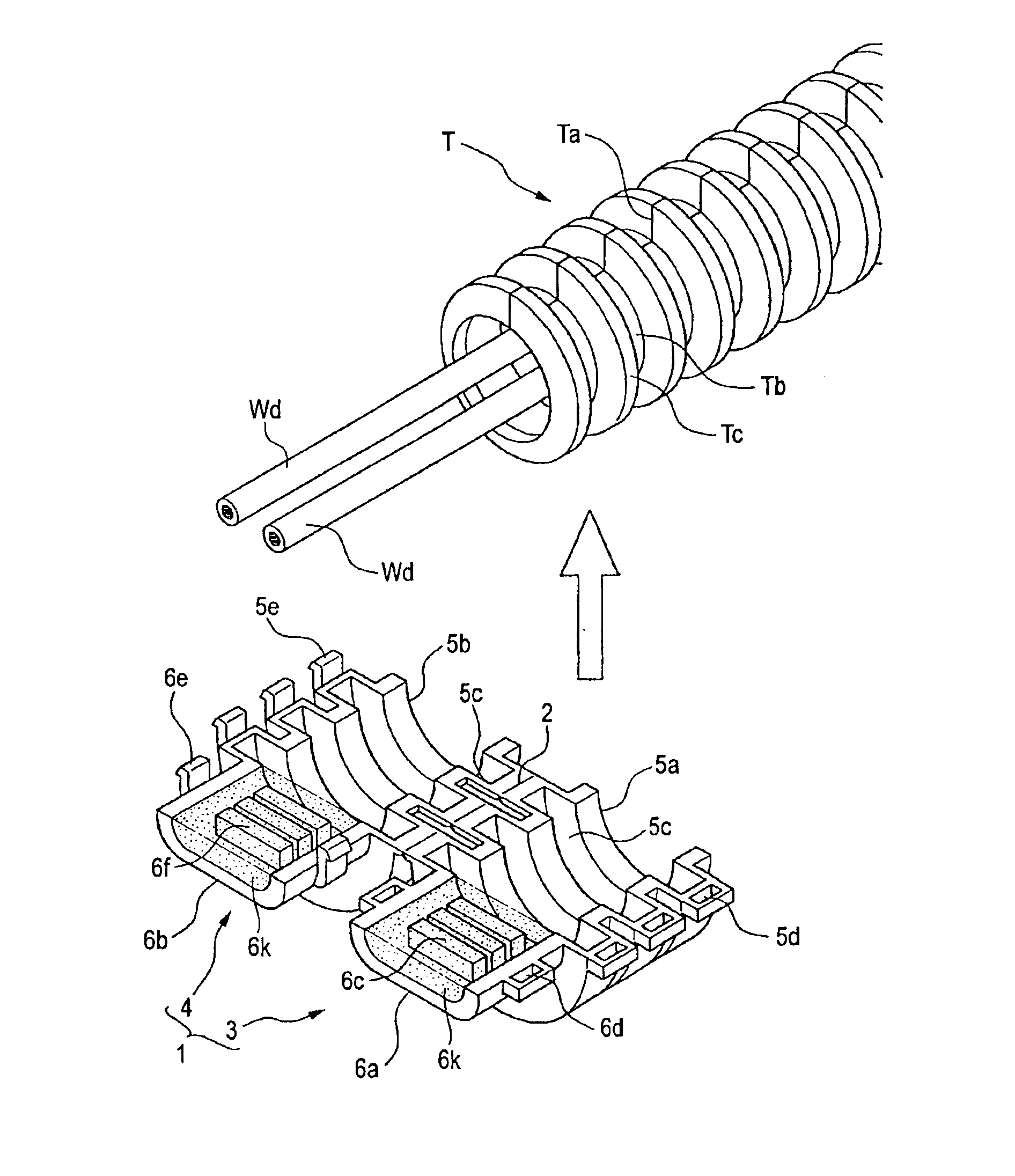
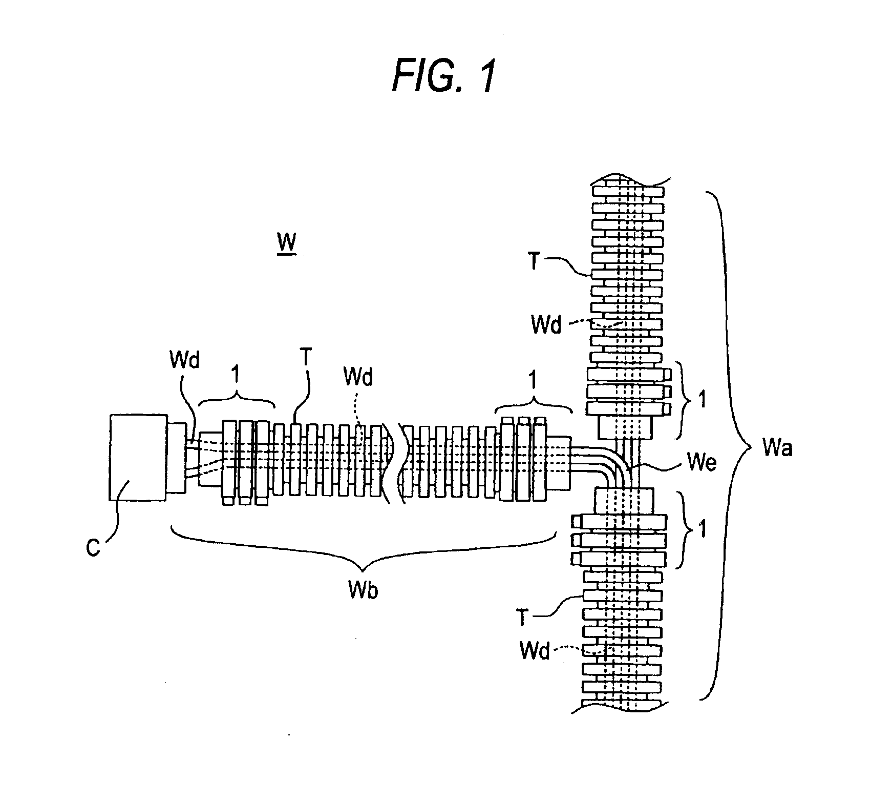
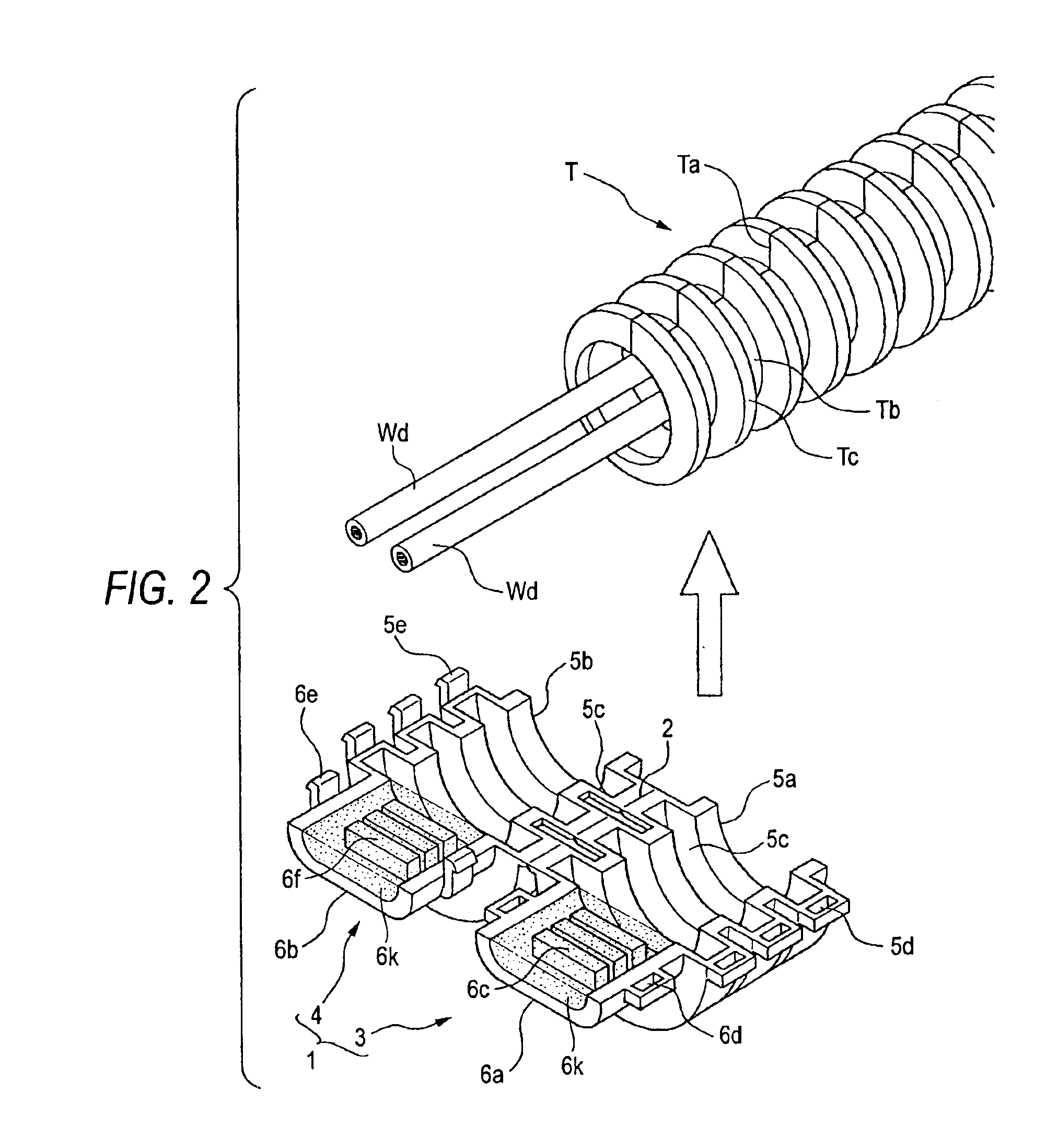
A first embodiment is explained referring to FIGS. 1 through 15. FIG. 1 is a view showing the schematic structure of a wire harness W in which the joint 1 is mounted, FIGS. 2 through 4 are views showing steps for mounting the joint 1 to an end portion of a corrugated tube T, FIGS. 5 through 13 are views showing three modifications of the joint 1 for respective mounting steps, and FIGS. 14 and 15 are views showing modes of utilization of the joint 1.

The wire harness W includes a trunk line Wa which bundles a plurality of cables Wd and extends longitudinally in the drawing and a branch line Wb which is formed by branching a portion of the cables Wd which constitute the trunk line Wa and extends laterally in the drawing. A connector C is connected to a distal end of the branch line Wb branched from the trunk line Wa. Three corrugated tubes T are exteriorly mounted on the trunk line Wa and the branch line Wb respectively.

The corrugated tube T is a hollow tube having bellows and is form...

second embodiment

The joint 10 of the second embodiment is formed in a hollow shape by molding using a synthetic resin material. The joint 10 is mounted on the end portion of the hard tube T by joining half-split halves 12, 13 which are connected by a hinge 11. The joint 10 before mounting is usually in a state that the half-split halves 12, 13 are opened. Each half 12, 13 respectively includes a half-split grip portion 14a, 14b and a half-split clamp portion 6a, 6b, wherein the half-split grip portions 14a, 14b are connected to each other by the hinge 11 which is extended coplanar with a separation surface.

On inner peripheries of the half-split grip portions 14a, 14b which are fitted on the end portion of the hard tube Td from the outside, grip protrusions 14c which extend in the circumferential direction are formed in a projecting manner in four rows in the axial direction and an inner diameter of ridges of the grip protrusions 14c is set smaller than an outer diameter of the hard tube Td and hence...


PUM


Abstract

A grip portion is formed by a pair of half-split grip portions and grips an end portion of a tubular cable cover exteriorly mounted on a cable when the half-split grip portions are joined. A clamp portion is formed by a pair of half-split clamp portions and clamps the cable exposed from the end portion when the half-split clamp portions are joined. A clamp protrusion is formed on an inner surface of the clamp portion and clamps the cable exposed from the end portion by pressing the cable in a radial direction.

Description

BACKGROUND OF THE INVENTION1. Field of the InventionThe present invention relates to a joint for tubular cable cover that joints a tubular cable cover which covers a cable such as a wire harness, and more particularly to a joint which restricts a displacement of a tubular cable cover which covers the cable.2. Description of the Related ArtConventionally, cables which constitute a wire harness arranged inside of an engine room of a vehicle are covered by a cylindrical tubular cable cover such as a so-called corrugated tube or a so-called spiral tube in order to protect the cables from heat and dust and, at the same time, to prevent the cables from coming into contact with peripheral parts.For example, the corrugated tube is formed by molding using a synthetic resin material such as polypropylene which has an excellent shock resistance characteristic and an excellent wear resistance characteristic. The corrugated tube is formed in a thin cylindrical shape, has the bellow structure in ...

Claims


Application Information

Patent Timeline
Patent Type & Authority Patents(United States)
IPC IPC(8): H02G3/02H02G3/04H02G3/06F16L33/00F16L33/28H02G3/30
CPCH02G3/06H02G3/0468H02G3/0418
Inventor SUDO, HIROSHITATOH, NOBUYOSHI
Owner AUTONETWORKS TECH LTD
Why Eureka
Try Eureka