Portable combustion-engined power tool and a method of operating same

a technology of power tools and combustion engines, which is applied in the direction of engine components, hot gas positive displacement engine plants, mechanical equipment, etc., can solve the problems of affecting the fuel-air ratio , difficult control of the amount of air mass brought into the combustion chamber to obtain the required ratio , too little or too much air mass available, etc., to achieve the effect of favorable energy conversion

Inactive Publication Date: 2005-04-12
HILTI AG
View PDF5 Cites 7 Cited by
  • Summary
  • Abstract
  • Description
  • Claims
  • Application Information

AI Technical Summary

Benefits of technology

is to provide a method of controlling a portable, combustion-engined tool which would insure a mo

Problems solved by technology

Controlling the amount of the air mass brought into the combustion chamber to obtain the required ratio λ is very difficult because of the interrupted flow of air during the tool operation.
With an unfavorable fuel pressure ratios at temperatures at and below 0° C

Method used


Image

  • Portable combustion-engined power tool and a method of operating same
  • Portable combustion-engined power tool and a method of operating same
  • Portable combustion-engined power tool and a method of operating same

Examples


Embodiment Construction

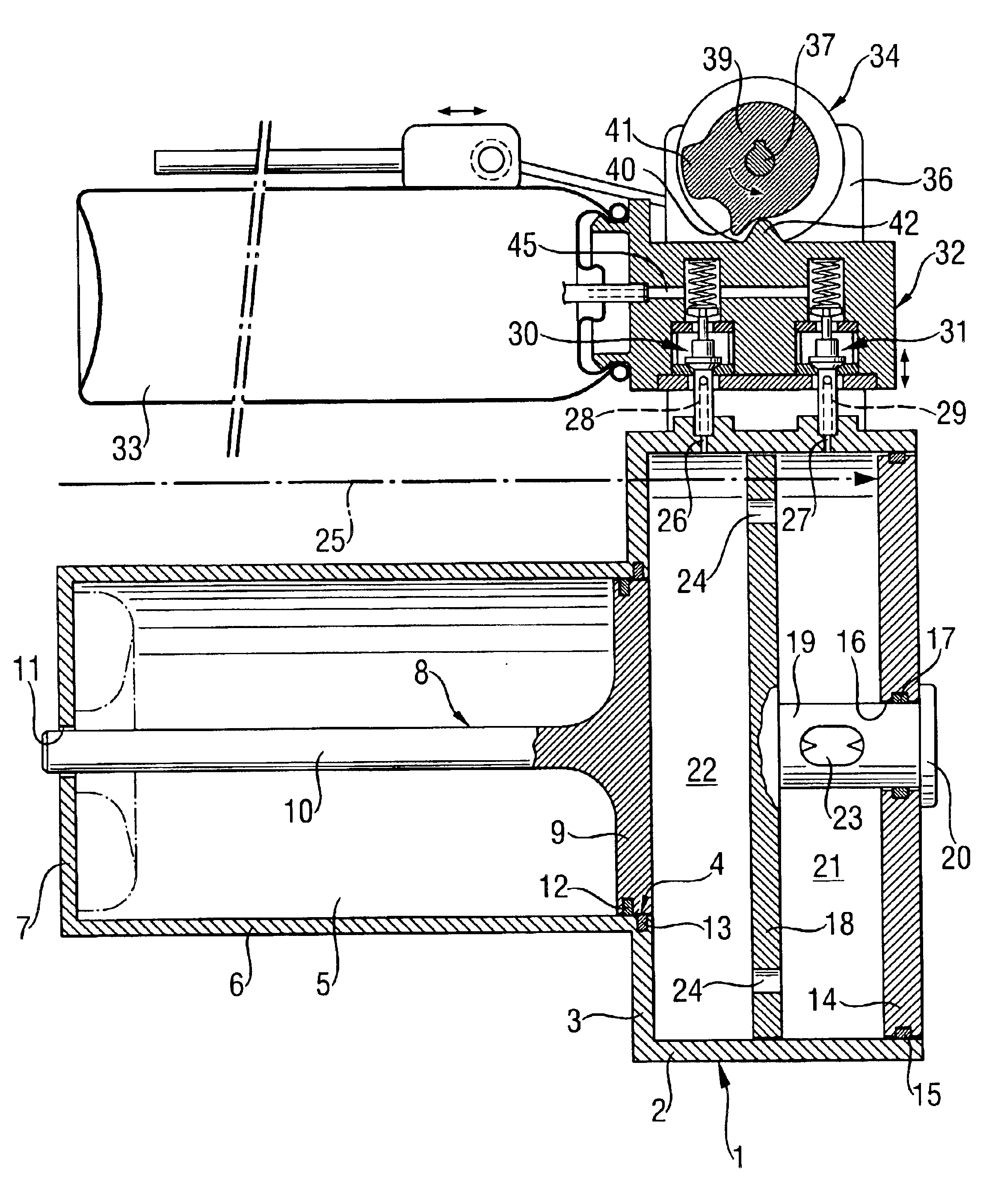
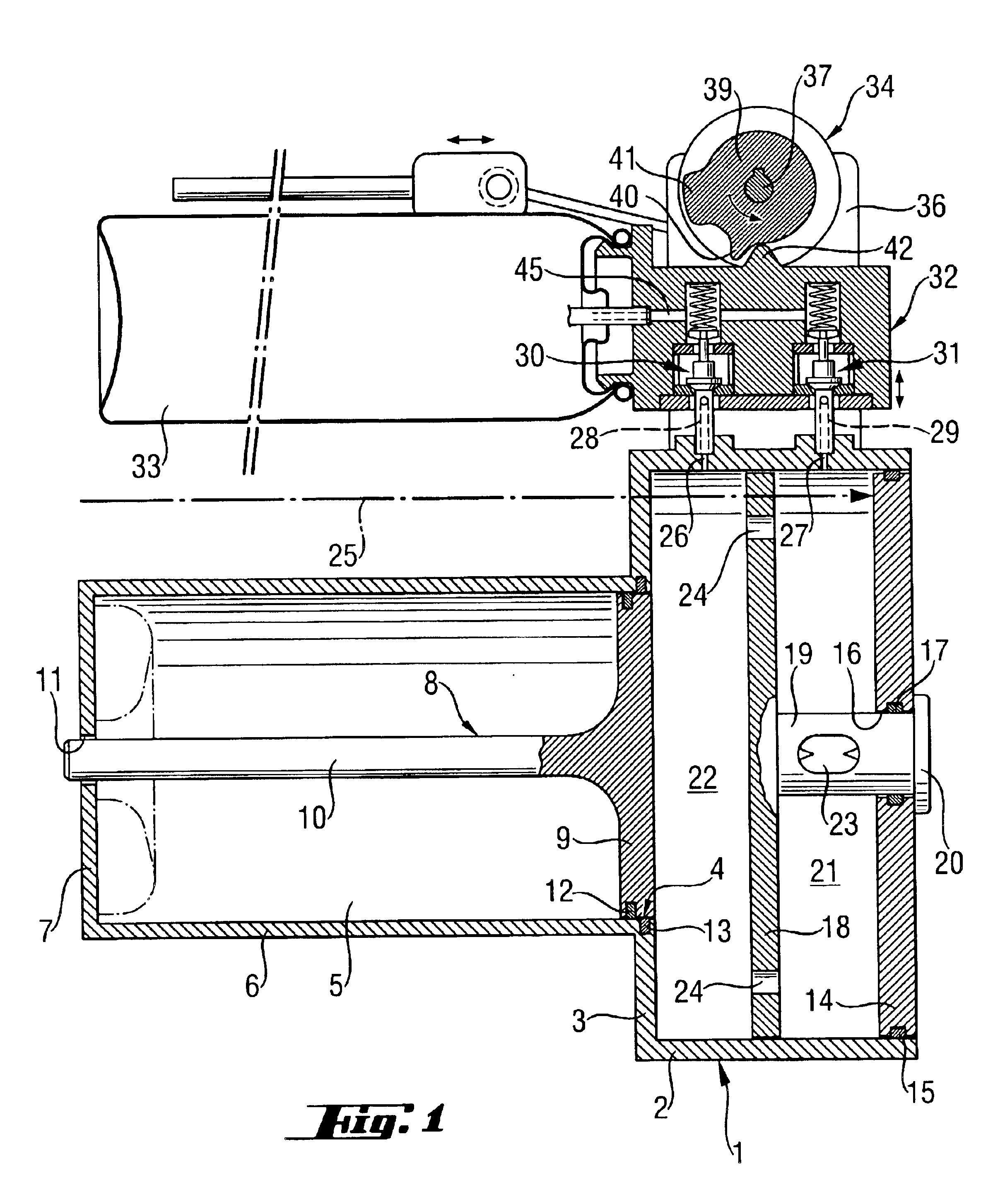
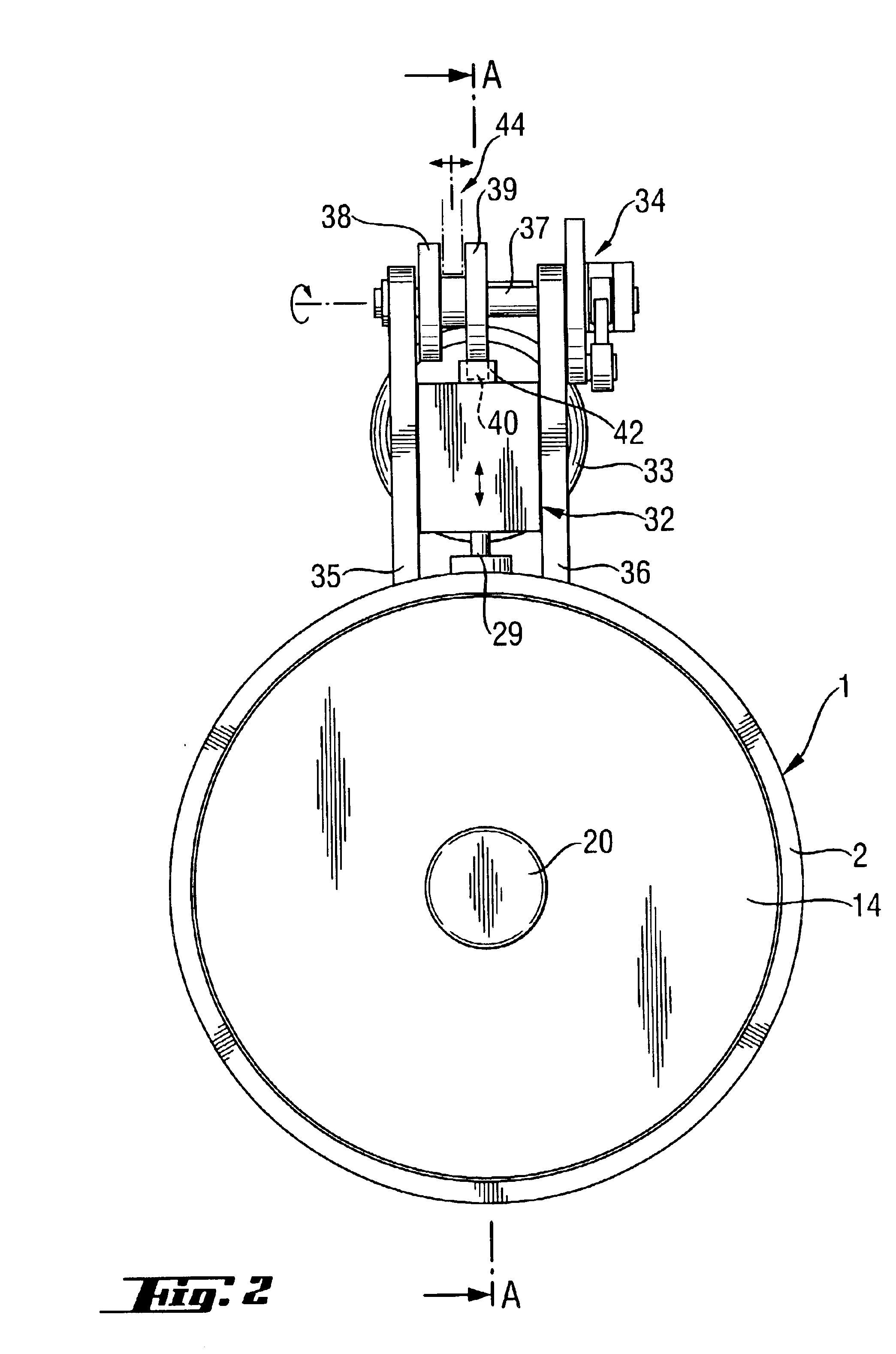
FIG. 1 shows a cross-sectional view of a combustion-engined setting tool for fastening elements along line A—A in FIG. 2 in the region of the tool combustion chamber. The setting tool shown in FIGS. 1-2 has a combustion chamber 1 having a cylindrical side wall 2 and a bottom wall 3. In the center of the bottom wall 3, there is provided an opening 4. A guide cylinder 5, which has a cylindrical wall 6 and a bottom wall 7, adjoins the bottom wall 3 of the combustion chamber 1 in the region of the central opening 4. A piston 8 slidably displaces in the guide cylinder 5 in a longitudinal direction of the guide cylinder 5. The piston 8 is formed of a piston plate 9 adjoining the combustion chamber and a piston rod 10 that is connected with the plate 9 in the center of the plate 9 and projects partially through the opening 11 in the bottom wall 7 of the guide cylinder 5.

FIG. 1 shows the piston in its initial, rearward position when the setting tool is not operated. The piston plate 9 adjoi...


PUM


Abstract

A method of controlling operation of a portable, combustion-engined, power tool and including feeding fuel into the combustion chamber of the power tool, before ignition, several times one after another in accordance with an intermittent metering operational mode, and a power tool including a control device (34, 64) for controlling operation of the fuel feeding device (32, 33) of the power tool so that the feeding device (32, 33) feeds the fuel into the combustion chamber (1) several times in accordance with the intermittent metering operational mode.

Description

BACKGROUND OF THE INVENTION1. Field of the InventionThe present invention relates to a portable, combustion-engined power tool, in particular a setting tool for fastening elements, and including a combustion chamber, a device for feeding fuel into the combustion chamber to obtain therein a combustible air-fuel mixture, and an ignition device for igniting the air-fuel mixture that fills the combustion chamber. The present invention also relates to a method of controlling operation of such power tool.2. Description of the Prior ArtIn a power tool that is formed, e.g., as a nail setting combustion-engined tool, a drive is applied by a piston to a nail-like element for driving it in an object. An ignitable air-fuel gas mixture becomes available when the setting tool is pressed against the object. Upon actuation of a trigger or an actuation lever, an electrical spark is generated that ignites the air-fuel gas mixture, starting the combustion process. The chemically bound energy of the fu...

Claims


Application Information

Patent Timeline
IPC IPC(8): B25C1/08B25C1/00F02N17/00F02B63/02F02N15/00F02B63/00F02N99/00
CPCB25C1/08F02B63/02F02N99/006F02N15/00F02D2400/06
Inventor VOELKER, LOTHARWOLF, IWAN
Owner HILTI AG
Why Eureka
Try Eureka