Diaphragm for bonded element sensor

Active Publication Date: 2005-04-12
HONEYWELL INT INC
View PDF6 Cites 87 Cited by
  • Summary
  • Abstract
  • Description
  • Claims
  • Application Information

AI Technical Summary

Benefits of technology

Other advantages and features will appear hereinafter.
The present invention provides a pressure sensor for producing a signal indicative of a pressure of a fluid to be monitored. The pressure sensor includes a housing having a fluid conduit for receiving the fluid to be monitored, and a diaphragm positioned at an end of the fluid conduit and including at least first and second portions, wherein a thickness of the first portion is less than a thickness of the second portion. The sensor also includes a transducer bonded to a surface of the first portio

Problems solved by technology

Others are impossible to correct and add unpredictable variation to pressure measurement.
While correctable errors are somewhat problematic for the transducer manufacturer, it is the non correctable errors that cause concern for the transducer user.
Environmental effects such as humidity, that can affect the accuracy of a transducer can be unrepeatable, and are much more difficult or impossible for the transducer manufacturer to predict and correct.
The degree of stress applied is different in each application and is hard to predict.
If the raw sensor element and package are not designed to reject such stresses, it will be impossible for the manufacturer to eliminate th

Method used


Image

  • Diaphragm for bonded element sensor
  • Diaphragm for bonded element sensor
  • Diaphragm for bonded element sensor

Examples


Embodiment Construction

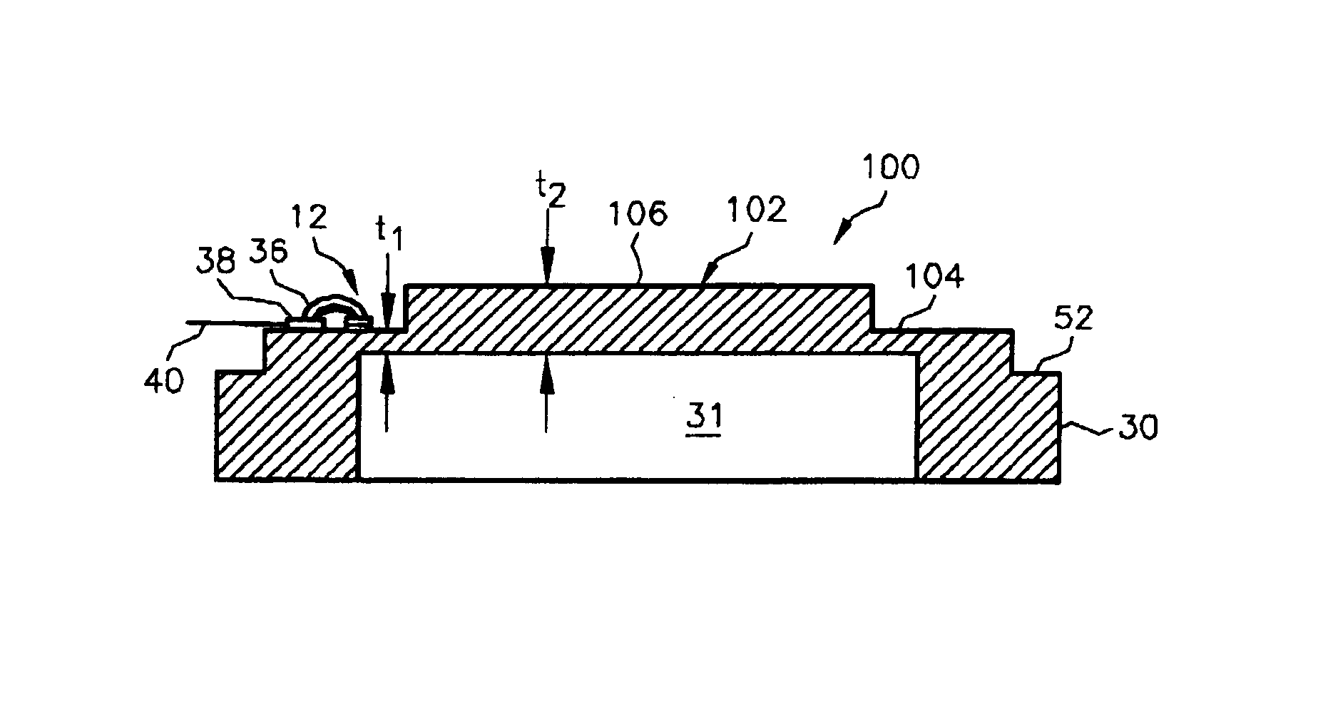
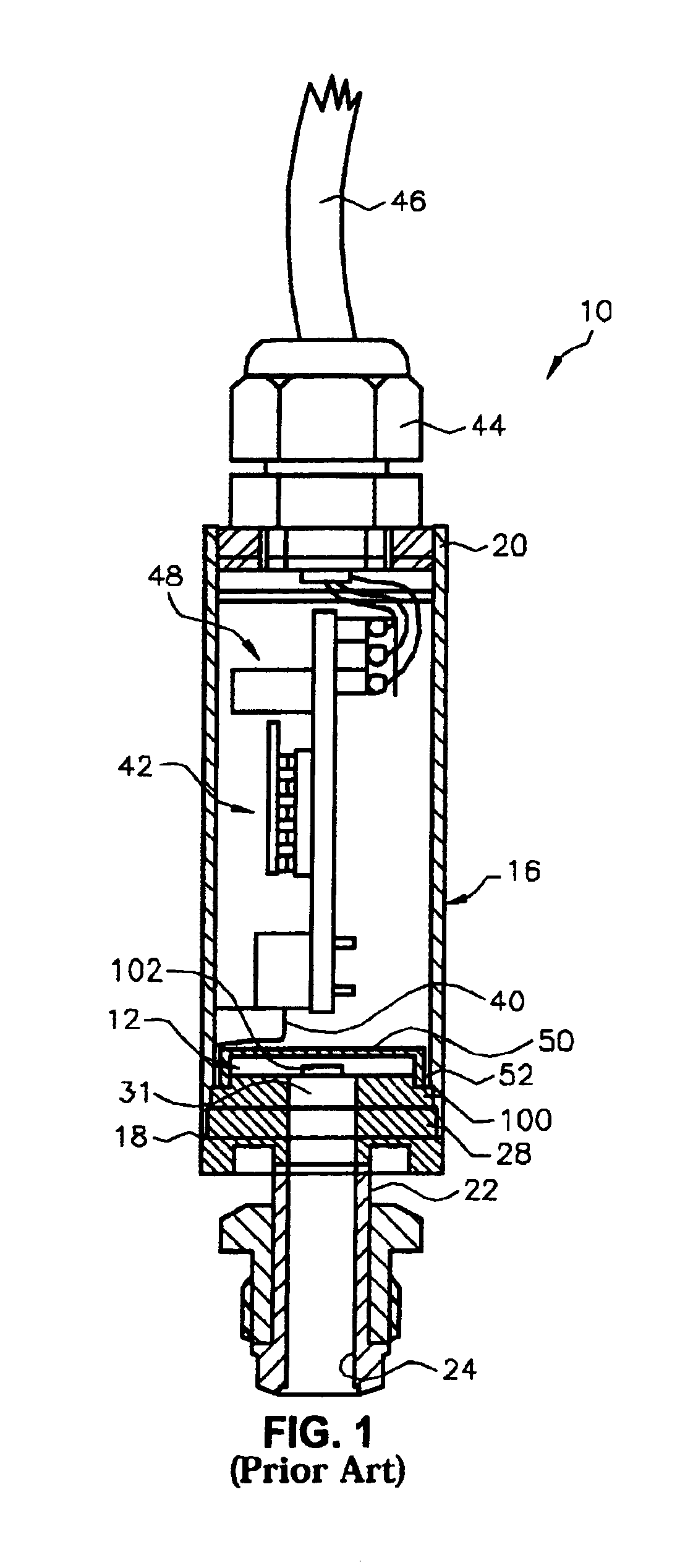
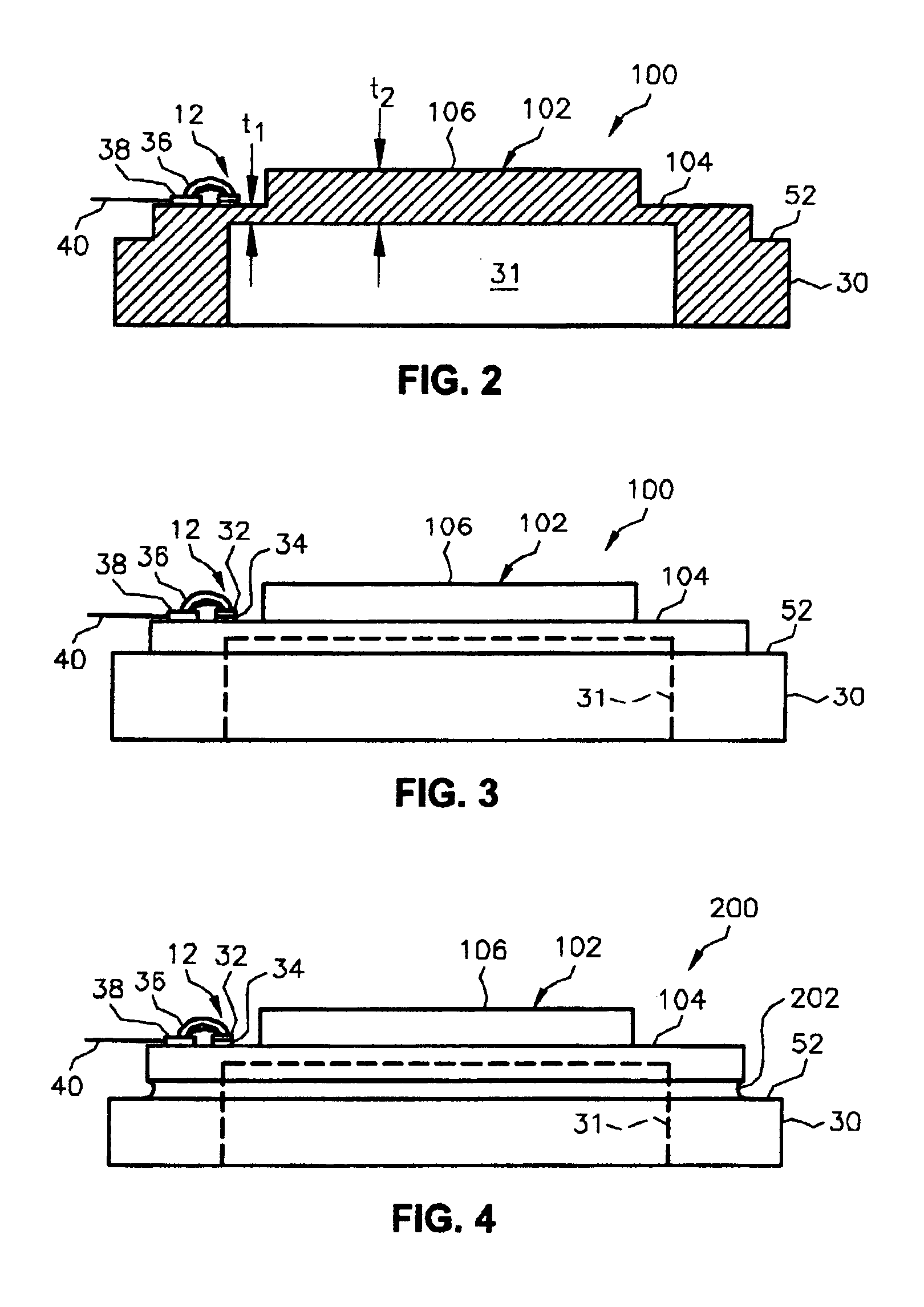
Referring to FIG. 1, an exemplary embodiment of an ultra-high-purity gas pressure sensor assembly 10 constructed in accordance with the present invention is shown. The pressure sensor assembly 10 uses a microelectromechanical system (MEMS) pressure transducer 12 mounted on a stainless steel diaphragm 102 to measure the pressure of a fluid. The pressure transducer 12 is preferably mounted on the diaphragm 102 using a high temperature bonding process.

The pressure sensor assembly 10 includes a tubular housing 16 having first and second opposing ends 18, 20. A connector 22 seals the first end 18 of the housing 16 and defines a fluid conduit 24. The connector 22 enables the pressure sensor assembly 10 to be coupled to a pressure vessel or similar pressurized environment containing gas to be monitored, so that the fluid conduit 24 communicates with the gas. An exemplary connector 22 is shown, but the pressure sensor assembly 10 can be provided with other types of process connectors.

A diap...


PUM


Abstract

A pressure sensor device for producing a signal indicative of a pressure of a fluid to be monitored, including a housing having a fluid conduit for receiving the fluid to be monitored and a diaphragm positioned at an end of the fluid conduit. The diaphragm includes at least first and second portions, wherein a thickness of the first portion is less than a thickness of the second portion. A transducer is bonded to a surface of the first portion of the diaphragm and including piezoresistive elements for sending the signal. Preferred is a circular second portion and an annular first portion around the outer edge of the second portion. The housing is preferably tubular and includes an annular shoulder for mounting the diaphragm, along with an annular groove on the outer surface of the first portion and connecting the first portion to the annular shoulder.

Description

FIELD OF THE INVENTIONThe present invention relates in general to sensor assemblies that include bonded element semiconductor transducers and, more particularly, to a diaphragm that supports the bonded element semiconductor transducer within the sensor assembly.BACKGROUND OF THE INVENTIONPressure transducers are widely used in the semiconductor industry for ultra-high-purity gas pressure measurement in process lines. A pressure transducer develops an electrical signal that is proportional to the pressure applied. An ideal pressure transducer design minimizes the effects of temperature, mechanical stress, and aging on the output signal so as not to compromise the semiconductor fabrication process. In actuality, transducers respond to environmental effects, and only some of the effects can be easily compensated through signal conditioning. Others are impossible to correct and add unpredictable variation to pressure measurement.Correctable errors are typically proportional to temperatu...

Claims


Application Information

Patent Timeline
IPC IPC(8): G01L7/02G01L7/08G01L9/00
CPCG01L9/0052
Inventor LEWIS, BRIAN D.
Owner HONEYWELL INT INC
Why Eureka
Try Eureka