Spark-ignition engine controller

a technology of spark ignition and engine controller, which is applied in the direction of electric control, ignition automatic control, manual lubrication, etc., can solve the problems of not being cost-effective, not contributing to the work, and the combustion speed becomes too slow, so as to improve fuel economy, reduce emissions, and the effect of widening the operating rang

Inactive Publication Date: 2005-04-12
MAZDA MOTOR CORP
View PDF8 Cites 29 Cited by
  • Summary
  • Abstract
  • Description
  • Claims
  • Application Information

AI Technical Summary

Benefits of technology

The present invention is based on such technology, and it is an object thereof to provide a spark-ignition engine controller which can effectively enable combustion through compression ignition in a following cylinder in an even greater operating range while suppressing heavy knocking, and hence improve fuel economy and reduce emissions.
According to the aforementioned form of the present invention, when the special operation mode is set in a partial operating range of the engine and combustion is performed in the following cylinder by compression ignition, the effects of an improvement in thermal efficiency due to lean-burn and an improvement in fuel economy due to a reduction in pumping loss are obtained in the preceding cylinder, and the effects of an improvement in combustion efficiency due to the reduction of cooling loss and cycle loss caused by HCCI under heavy EGR and an improvement in fuel economy due to a reduction in pumping loss are obtained in the following cylinder. When it is confirmed that the engine is in an operating condition where heavy knocking is likely to occur within the compression ignition range of the following cylinder, the timing of fuel injection into the following cylinder is relatively retarded, and thus activation of the air-fuel mixture is suppressed, effectively preventing the occurrence of heavy knocking caused when the ignitability of the mixture is too good. When it is confirmed that the engine is in an operating condition where heavy knocking is unlikely to occur within the compression ignition range of the following cylinder, the timing of fuel injection into the following cylinder is relatively advanced, thereby encouraging activation of the air-fuel mixture. As a result, misfires in the following cylinder are effectively prevented, an improvement in thermal efficiency due to compression ignition is obtained, and the engine output can be sufficiently ensured.

Problems solved by technology

In such conventional engines which perform lean operations, the aforementioned lean NOx catalyst must be provided in the exhaust passage to maintain the NOx purification ability during a lean operation, which is not cost-effective.
Furthermore, if the air-fuel ratio of the mixture becomes lean to or above a certain extent, the combustion speed becomes too slow and combustion near the final combustion phase does not contribute to the work.
Hence improvements in fuel economy through lean stratified charge combustion are limited.
In a typical spark-ignition gasoline engine, however, forced ignition is required for combustion, and thus the temperature and pressure inside the combustion chamber in the vicinity of compression top dead center cannot be raised to an extent at which compression ignition occurs.
In order to cause compression ignition, specific measures must be taken to greatly raise the temperature or pressure inside the combustion chamber, but in the past it has been difficult to raise the temperature or pressure inside the combustion chamber to an extent at which compression ignition occurs in the partial load range at which fuel economy improvement is required while avoiding irregular combustion caused by heavy knocking in the high-load range, or in other words spontaneous ignition of the air-fuel mixture before the flame propagates through the combustion chamber.

Method used


Image

  • Spark-ignition engine controller
  • Spark-ignition engine controller
  • Spark-ignition engine controller

Examples


Embodiment Construction

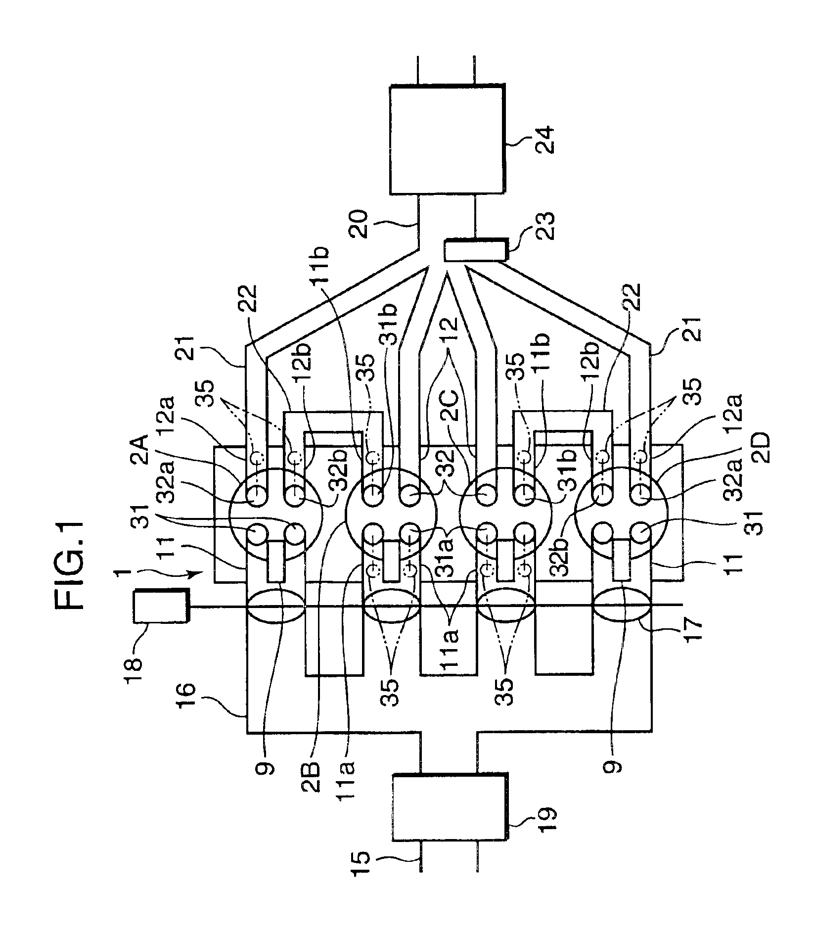
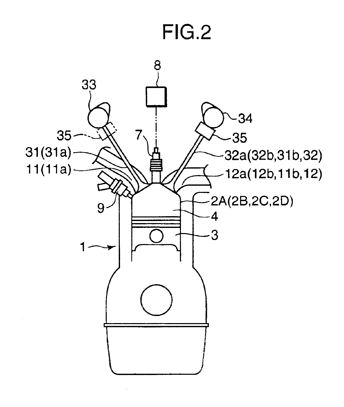
FIG. 1 shows the schematic constitution of an engine according to an embodiment of the present invention, and FIG. 2 shows in outline the constitution of one cylinder of an engine body 1 and an intake valve, exhaust valve, and the like provided thereon. In these drawings, the engine body 1 comprises a plurality of cylinders, and in the illustrated embodiment comprises four cylinders 2A to 2D. A piston 3 is inserted into each of the cylinders 2A to 2D, and a combustion chamber 4 is formed above the piston 3.

A spark plug 7 is provided at the apex of the combustion chamber 4 of each cylinder 2, and the tip end of the spark plug faces the interior of the combustion chamber 4. An ignition circuit 8 which is capable of controlling the ignition timing through electronic control is connected to the spark plug 7.

A fuel injector 9 for injecting fuel directly into the combustion chamber 4 is provided on a side portion of the combustion chamber 4. The fuel injector 9 is equipped with a needle v...


PUM


Abstract

Intake air / exhaust gas flow control is performed in an partial load range of an engine such that burned gas which is discharged from an exhaust stroke side preceding cylinder of a pair of cylinders having an overlapping exhaust stroke and intake stroke is introduced into an intake stroke side following cylinder through an intercylinder gas channel. In an operating range set as a special operation mode, a combustion condition controller executes control such that combustion is performed in the following cylinder by means of compression ignition. In an operating condition in which knocking is likely to occur within the compression ignition range of the following cylinder, control is executed by a fuel injection controller such that the timing of fuel injection into the following cylinder is retarded relative to that of an operating condition in which knocking is unlikely to occur.

Description

BACKGROUND OF THE INVENTION1. Field of the InventionThe present invention relates to a spark-ignition engine controller, and more particularly to a device for controlling the combustion condition in each cylinder of a multi-cylinder engine in order to improve fuel economy and reduce emissions.2. Description of the Related ArtConventional technology for improving fuel economy in a spark-ignition engine by performing combustion with the air-fuel ratio of the air-fuel mixture in each cylinder set to a lean air-fuel ratio which is larger thin the stoichiometric air-fuel ratio is well known. It is also known that by providing a fuel injector for injecting fuel directly into a combustion chamber and performing stratified charge combustion by injecting fuel from the fuel injector in the compression stroke when the engine is being operated in a low-speed low-load range or the like, ultra lean combustion can be realized (see Japanese Unexamined Patent Application Publication H10-274085 for e...

Claims


Application Information

Patent Timeline
Patent Type & Authority Patents(United States)
IPC IPC(8): F01L1/26F02B75/20F02D41/00F02D41/14F02B47/00F02D13/02F02D13/06F01L1/18F02B17/00F02D41/30F01L13/00F02B75/00F02P5/04F02M25/07F02F1/42F02B47/10F02D41/34F16N3/12F16N3/00F02B23/10F02B1/12F02B75/12F02B75/18F02B1/00F02D41/02F02D41/04F02D41/22F02D41/38F02D41/40F02D43/00
CPCF01L1/267F01L13/0036F02B17/005F02B47/10F02B75/20F02D13/0207F02D13/0276F02D13/06F02D41/0002F02D41/0057F02D41/008F02D41/1475F02D41/3017F02D41/3029F02D41/3035F02F1/4214F02M25/0749F02M25/0752F02P5/045F16N3/12F01L13/0005Y02T10/47F01L2800/00F02B1/12F02B23/104F02B2075/125F02B2075/1816F02B2275/18F02D41/1454F02D41/187F02D2041/0015F02P5/1527Y02T10/146Y02T10/18Y02T10/123Y02T10/42F02M26/43F02M26/01Y02T10/12Y02T10/40
Inventor HITOMI, MITSUOSUMIDA, KOUJIHAYASHI, TAKAYOSHI
Owner MAZDA MOTOR CORP
Why Eureka
Try Eureka