Construction machine and milling roller

a construction machine and roller technology, applied in the direction of cutting machines, tilling equipment, ways, etc., can solve the problems of high labor intensity, low efficiency, and troublesome roller exchange, and achieve the effect of reducing labor intensity, facilitating the exchange of milling rollers, and simplifying the handling of demounted milling rollers

Inactive Publication Date: 2005-04-12
WIRTGEN GMBH
View PDF10 Cites 48 Cited by
  • Summary
  • Abstract
  • Description
  • Claims
  • Application Information

AI Technical Summary

Benefits of technology

It is the object of the invention to provide a milling roller and a construction machine which allow for a fast exchange of milling rollers and a simplified handling of the demounted milling rollers and which minimize the time and work required for the exchange of a milling roller.

Problems solved by technology

Presently, however, the exchange of the rollers is very bothersome and necessitates special auxiliary tools for the mounting and dismounting of the milling roller.
In this approach, it is disadvantageous that the milling rollers are driven hydrostatically by hydraulic motors arranged on both sides of the milling roller.
According to this concept, the milling roller is provided with a hydrostatic drive which due to its system-inherent disadvantages, e.g. low efficiency, is nowadays hardly used any more in road milling.
A further disadvantage of this approach resides in that the milling tubes have to be axially fixed by means of annular shoulders so that the fastening elements are located in the region of the strongest contamination.
Disadvantages reside in the considerable expenditure for the screw connections and in that, due to the constant diameter of the base body, the milling depth is restricted when a planetary gear is integrated into the base body.
In this approach, it is disadvantageous that different milling processes, such as normal and fine milling, cannot be performed without exchanging the milling rotor.
A problem in the above mentioned state of the art normally resides in that the fastening elements for fixing the milling element to the base body are provided in the surface region of the cylindrical milling tool.
Exactly this region, however, is subjected to massive contamination so that the exchange of the milling tube is rendered considerably difficult.

Method used


Image

  • Construction machine and milling roller
  • Construction machine and milling roller
  • Construction machine and milling roller

Examples


Embodiment Construction

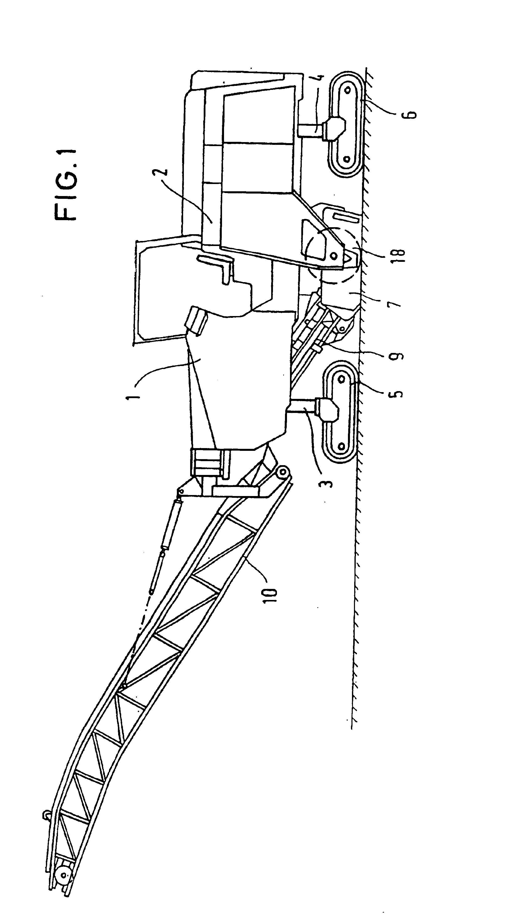
FIG. 1 illustrates a road milling machine 1 for which the invention described hereunder is primarily used. Road milling machines normally comprise a chassis 2 with an internal combustion engine 11 mounted therein. The chassis of the machine normally comprises lifting columns 3, 4, being adjustable in height and having support wheels or running chains 5,6 mounted thereon.

The milling aggregate 7 with the milling roller 18 is arranged under the chassis 2 and is rigidly connected thereto. The material detached by the milling roller is conveyed onto a first conveyer belt 9 which passes the material on to a second conveyer belt 10 which is adjustable in height and pivotable.

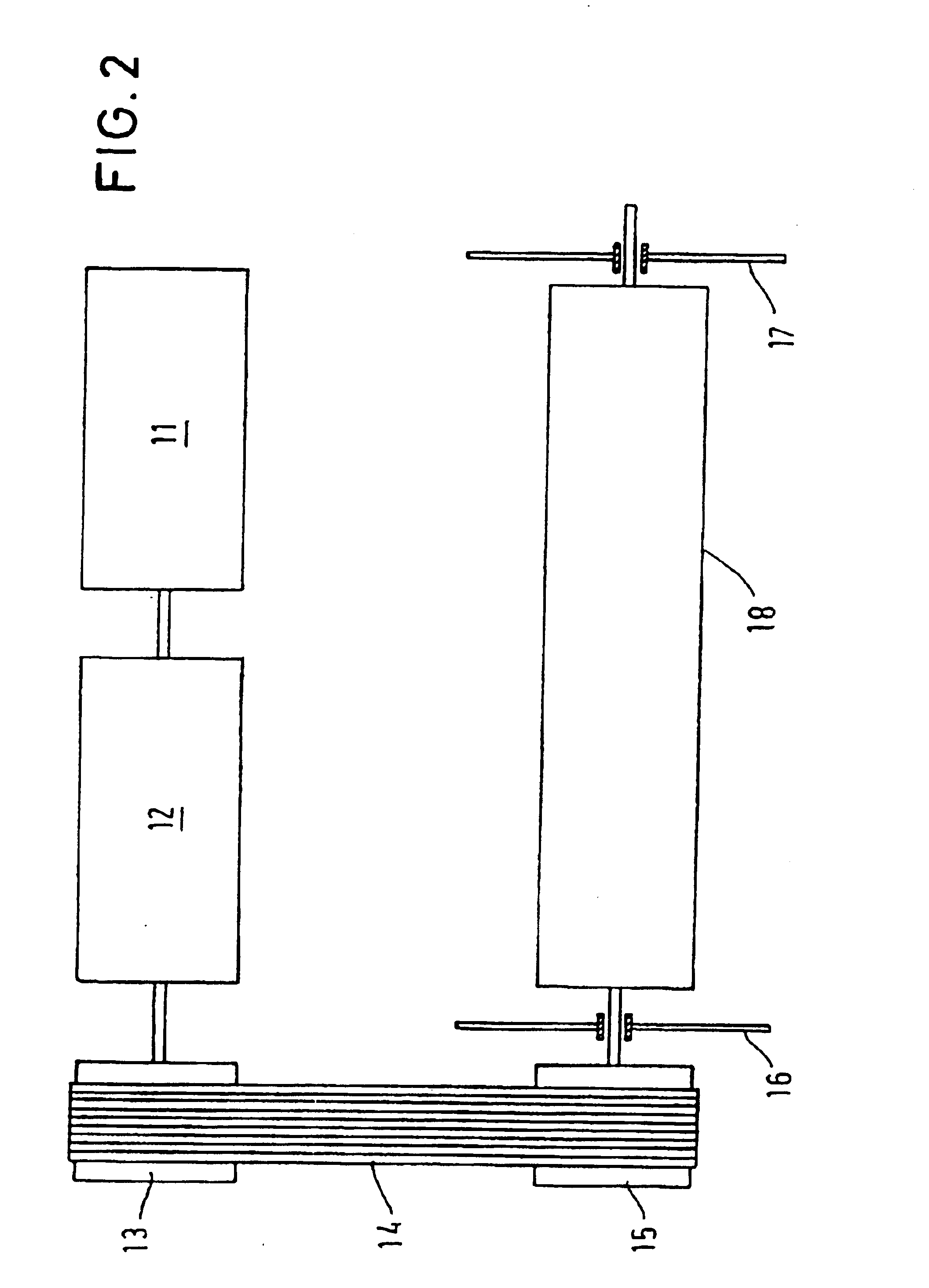
FIG. 2 illustrates the concept of the milling roller drive. An internal combustion engine 11 directly drives a pulley 13. Within this power train, there is normally arranged a pump distributor transmission 12 whereon the hydraulic pumps for the various hydrostatic drives are mounted. The engine power is transmitted via...


PUM


Abstract

In a construction machine comprising a machine frame (2) having a milling roller (18) arranged for rotation therein, the milling roller (18) comprising a roller base body (19) driven by a milling roller drive device (11 to 15) via a transmission unit (32), and a milling tube (25) to be coaxially mounted on the roller base body (19) and to be attached in a manner allowing exchange thereof, with the milling tube (25) carrying cutting tools on its outer surface (46), it is provided that the milling tube (25) comprises fastening elements (28), radially projecting from the inner surface (44), by which the milling tube (25) can be mounted in a rotationally fixed manner to the roller base body (19) or to a member connected to the roller base body (19).

Description

BACKGROUND OF THE INVENTIONDifferent situations at construction sites and different milling processes make it often necessary to adapt the milling tool to the specific tasks. For instance, when a specific surface roughness is to be obtained, a milling roller with a special line interval of the milling tools or a different tool equipment will be required. In another application, only lanes of specific widths have to be built, thus requiring a milling roller of a specific working width.Normally, in such situations, a special milling machine has to be used, or the machine must be equipped with a milling roller adapted to the task. Presently, however, the exchange of the rollers is very bothersome and necessitates special auxiliary tools for the mounting and dismounting of the milling roller.The adapting of milling rollers to different requirements is known in the state of the art.DE 40 37 448 A describes a road milling machine wherein the roller body is braced between a fixed bearing c...

Claims


Application Information

Patent Timeline
Patent Type & Authority Patents(United States)
IPC IPC(8): E01C23/088E01C23/00E01C23/12E02F3/06
CPCE01C23/088E01C23/12
Inventor GAERTNER, OLAFHAEHN, GUENTERHOLL, BERND
Owner WIRTGEN GMBH
Why Eureka
Try Eureka