
Short body endoprosthesis

a short-body, endoprosthesis technology, applied in the field of vascular disorders, can solve the problems of substantial surgical intervention, substantial risk of rupture and death, and surgery itself can be taxing and dangerous for patients, so as to reduce the risk of rupture, reduce the pressure on the weakened tissue wall, and enhance the security of the trunk engagement

Inactive Publication Date: 2005-04-12
CR BARD INC
View PDF15 Cites 76 Cited by
  • Summary
  • Abstract
  • Description
  • Claims
  • Application Information

AI Technical Summary

Benefits of technology

"The invention is an improved endoprosthetic implant that can be placed within a torturous body lumen to treat vascular disorders such as aneurysms. The implant is designed to be easily positioned and repositioned within the body lumen and can be assembled in a patient's body. It includes a trunk and a leg extension that can be connected to form a continuous fluid path for carrying blood and reducing pressure on the weakened tissue wall. The implant can be secured to the walls of the body lumen using hooks or other suitable devices. Overall, the invention provides an improved and flexible endoprosthetic implant for treating vascular disorders."

Problems solved by technology

Many of these diseases are life-threatening conditions that demand substantial surgical intervention.
For example, an aortic aneurysm is a particularly troubling medical condition in which a localized abnormal dilation of the aorta occurs.
At the site of the dilation the aorta wall becomes thin and weak, giving rise to a substantial danger of rupture and death by internal hemorrhaging.
Although there are traditional surgical procedures that can be effective in treating conditions like an aortic aneurysm, the surgery itself can be taxing and dangerous for the patient.
This is a highly invasive and dangerous surgical procedure that requires that the surgeon balance the patient's risk of harm from the aneurysm against the patient's risk of harm from the treatment.
However, more aneurysms are left untreated than treated as much of the afflicted population is ill or frail and therefore unlikely to survive the surgery.
In these systems, the treating surgeon uses one or more catheters to deliver the graft to the site of the aneurysm and in a cumbersome process the surgeon releases the graft from the catheters and arranges the main body of the graft within the aorta and the legs within the two iliac arteries.
Although these modular endovascular grafts can provide an effective treatment, their application is generally limited to aneurysms that occur within aortas that are substantially straight and only moderately transverse to the patient's iliac arteries.
However, an unfortunate side effect of some vascular diseases, including aneurysms, is that tissue growth can occur at the site of the diseased vessel.
This can cause the diseased aorta to lengthen.
For several reasons, patients with twisted aortas are often poor candidates for receiving modular endovascular grafts through transluminal delivery.
For example, it may be difficult for the surgeon to achieve the necessary alignment for delivering the different pieces of the modular endovascular graft.
Further, the twisted aorta often has only a short renal neck of healthy tissue to which the main body of the graft may attach.
Therefore, the surgeon may only be able to place a limited portion of the main graft body into the short renal neck, leaving a large section of the graft to extend into the aneurysm at an angle that can be significantly transverse to the iliac arteries through which the delivery catheter travels.
In these cases, it may not be possible for the surgeon to snake the guidewire that is used to deliver the other components of the modular graft through the iliac artery and into the portion of the modular endovascular graft that extends into the aneurysm.

Method used


Image

  • Short body endoprosthesis
  • Short body endoprosthesis
  • Short body endoprosthesis

Examples


Embodiment Construction

To provide an overall understanding of the invention, the methods, systems and devices of the invention will be discussed with reference to the application of treating an aortic aneurysm. However, it will be understood by persons of ordinary skill in the art that the general methods, systems and devices described herein are equally applicable to all cases in which implants are provided for carrying fluids within the body. These applications can include vascular grafts for treating other aneurysms, lesions, grafts for carrying urine, grafts for carrying bile, grafts for creating subcutaneous injection ports for receiving fluids such as therapeutic agents and saline solution, or any other application requiring an implant to be located in a lumen of a patient. Other clinical uses of the invention can be made without departing from the scope of the invention.

The invention comprises, inter-alia, endoprosthetic implants, a subset of which can include a class of endovascular grafts for tre...


PUM


Abstract

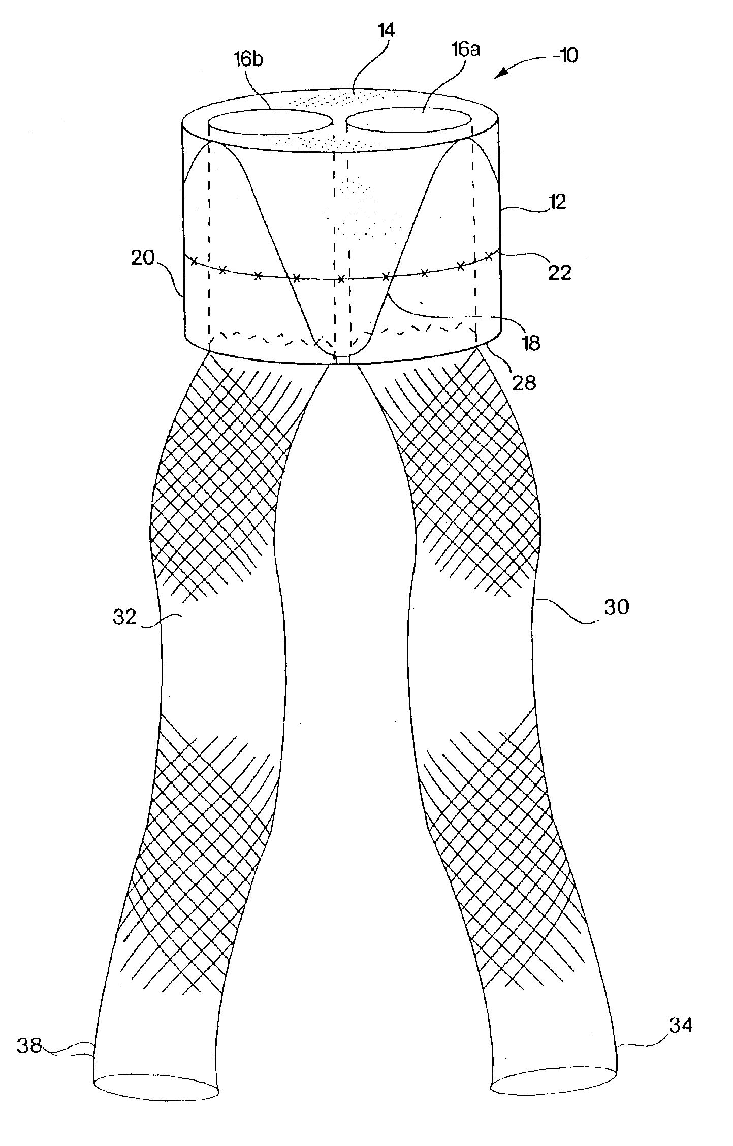
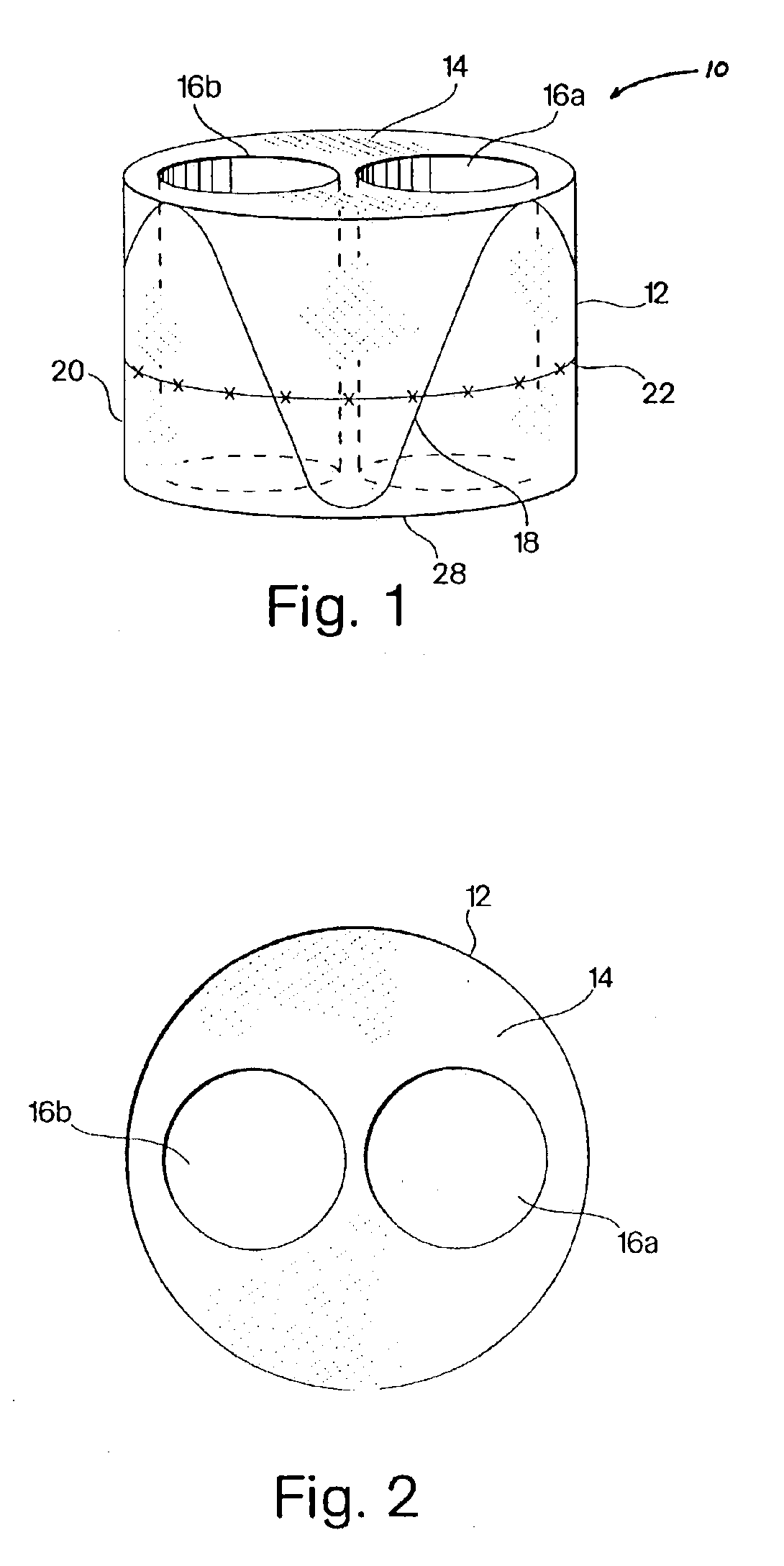
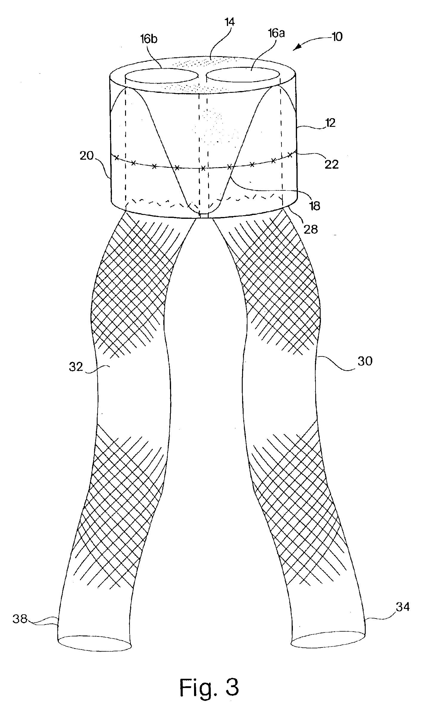
The invention comprises, inter-alia, endoprosthetic implants for treating vascular defects, including abdominal aortic aneurysms. Implants according to the invention have a short main body that can be positioned within a patient's aorta at a position above the renal end of an aortic aneurysm. The short main body includes a proximal, or renal, face that redirects the flow of blood into the openings of channels that can carry blood past the aneurysm. In this way, the flow of blood through the aorta is diverted into the two passageways and through the main body of the implant. Fluid exiting the implant can be carried by leg extensions and delivered to a healthy part of the patient's aorta or the iliac arteries. Accordingly, the implant provides a system for allowing blood traveling through the aorta to be carried by a vascular graft that spans an aortic aneurysm, thereby relieving fluid pressure on the thin wall of aortic aneurysm, and reducing the risk of death caused by a ruptured aneurysm.

Description

FIELD OF THE INVENTIONThe invention relates to systems and methods for treating vascular disorders, including conditions affecting bifurcated blood vessels.BACKGROUND OF THE INVENTIONDiseases of the vascular system afflict a substantial portion of the adult population. Many of these diseases are life-threatening conditions that demand substantial surgical intervention. For example, an aortic aneurysm is a particularly troubling medical condition in which a localized abnormal dilation of the aorta occurs. At the site of the dilation the aorta wall becomes thin and weak, giving rise to a substantial danger of rupture and death by internal hemorrhaging. Although there are traditional surgical procedures that can be effective in treating conditions like an aortic aneurysm, the surgery itself can be taxing and dangerous for the patient. In particular, for an aortic aneurysm the surgical procedure requires that the patient's abdominal cavity be opened to reach and expose the aortic aneury...

Claims


Application Information

Patent Timeline
Patent Type & Authority Patents(United States)
IPC IPC(8): A61F2/06
CPCA61F2/07A61F2002/065A61F2002/075A61F2220/0075A61F2220/005A61F2220/0066A61F2/89
Inventor KUJAWSKI, DENNISWEISER, MICHAEL F.
Owner CR BARD INC
Learn More