

Magnetic sensor
a magnetism detection and sensor technology, applied in the field of magnetism detection apparatuses, can solve the problems of increasing the amount of current to be fed to the coil, difficult to reduce power consumption, and few of them can achieve satisfactory levels of magnetism detection sensitivity, etc., to achieve the effect of improving high-precision and low-cost magnetism detection and reducing detection precision
- Summary
- Abstract
- Description
- Claims
- Application Information
AI Technical Summary
Benefits of technology
Problems solved by technology
Method used
Image

Examples
second embodiment
FIG. 9 is an exploded perspective view of a magnetism detection apparatus according to the present invention.
The second embodiment is characterized by the provision of two magnetic impedance elements 1a and 1b, in contrast with the one, shown in FIG. 1. As a consequence, it is possible to determine the output difference between the two magnetic impedance elements 1a and 1b, thereby making it possible to detect the actual magnetic field by canceling the adverse effect of the external disruptive magnetic field. As a result, it is possible to conduct detection with higher precision.
FIG. 10 is a schematic of drawing that will be used to help explain a method for canceling an external disruptive magnetic field.
In FIG. 10, based on the assumption that magnetic fields detectable by the magnetic impedance elements 1a and 1b against a magnetic field S are defined as Sa and Sb, and further, assuming that magnetic fields detectable by the magnetic impedance elements 1a and 1b against a steady ...
third embodiment
FIG. 11 is a perspective view of a magnetism detection apparatus according to the present invention.
The third embodiment is characterized by the provision of a micro-magnet 7 in place of the biasing coil 4 shown in FIG. 9. The micro-magnet 7 applies a DC bias current to the magnetic impedance elements 1a and 1b. This means that no current is drawn by the micro-magnet 7, which is opposite to the case in which a biasing coil is utilized. Normally, a current of approximately 30 mA is required for the biasing coil, and thus, during driving of the micro-magnet 7 with 5 V of power, it is possible to save approximately 150 mW of driving power.
FIGS. 12(a) to (f) show the characteristics of the DC bias current fed by the micro-magnet 7 shown in FIG. 11. The sensor output characteristics against the external magnetic field shown in FIG. 12 exhibit the characteristics of conventional magnetic impedance elements. This in turn illustrates that the optional sensor output can be obtained, based on...
fourth embodiment
FIG. 13 is a perspective view of a magnetism detection apparatus according to the present invention.
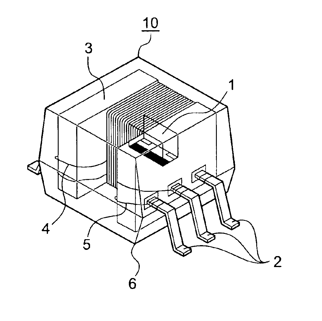
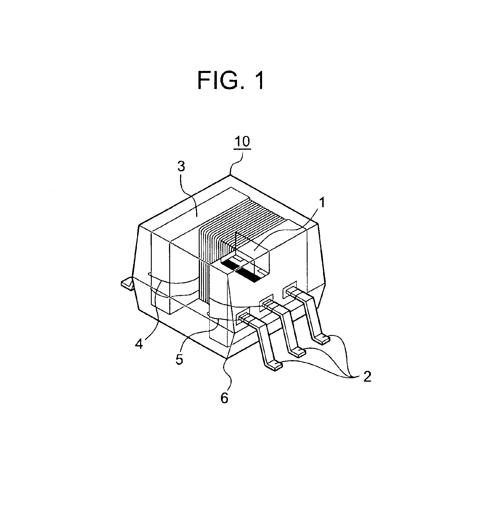
The fourth embodiment is characterized by the provision of the magnetism detection circuit 8 inside the magnetism detection apparatus, as shown in FIG. 3, in contrast with the constitution of the magnetism detection apparatus shown in FIG. 1. By virtue of this arrangement, it is possible to enhance the signal-to-noise (S / N) ratio of the sensor signals. Further, by internally storing a variety of corrective data obtained by the automatic calibration described earlier with reference to FIG. 4 for each magnetic impedance element 1, the magnetism detecting operation can be executed with much higher precision. As a matter of course, the magnetism detection circuit 8 is also applicable to the magnetism detection apparatuses shown in FIGS. 9 and 11.
According to the present invention, as a result of the integral assembly of the magnetic impedance elements, biasing coils, negative-feedback coi...
PUM
 Abstract
Description
Claims
Application Information