Magnetic resonance scanner with electromagnetic position and orientation tracking device

a technology of position tracking and magnetic resonance scanner, applied in the direction of magnetic variable regulation, instruments, applications, etc., can solve the problems of model failure, model also has no means to compensate for field distorting elements, same limitations, etc., and achieve the effect of avoiding line of sight limitations

Inactive Publication Date: 2005-04-12
JAKAB PETER D
View PDF98 Cites 131 Cited by
  • Summary
  • Abstract
  • Description
  • Claims
  • Application Information

AI Technical Summary

Benefits of technology

Systems and methods for determining the position and orientation of an object with an attached sensor in a magnetic resonance scanner are disclosed. In general magnetic resonance scanners acquire data about a target which reside within a homogenous region of a static magnetic field of the magnetic resonance scanner. In one embodiment of the invention, a magnetic resonance scanner is used

Problems solved by technology

When the physical dimensions of the generating and sensing elements are comparable to the separation between them, the model fails.
The model also has no means to compensate for field distorting elements, for example, the presence of conductive or ferro-magnetic material.
U.S. Pat. No. 4,849,692 further extends the method to utilize pulsed direct current (DC) magnetic fields in place of AC fields, but has the same limitations.
Because the magnetic field sensor must be within the quasi-linear section of the magnetic field of the Helmholtz coils, large coils are required for location tracking over the required area, therefore the presence of the magnetic resonance s

Method used


Image

  • Magnetic resonance scanner with electromagnetic position and orientation tracking device
  • Magnetic resonance scanner with electromagnetic position and orientation tracking device
  • Magnetic resonance scanner with electromagnetic position and orientation tracking device

Examples


Embodiment Construction

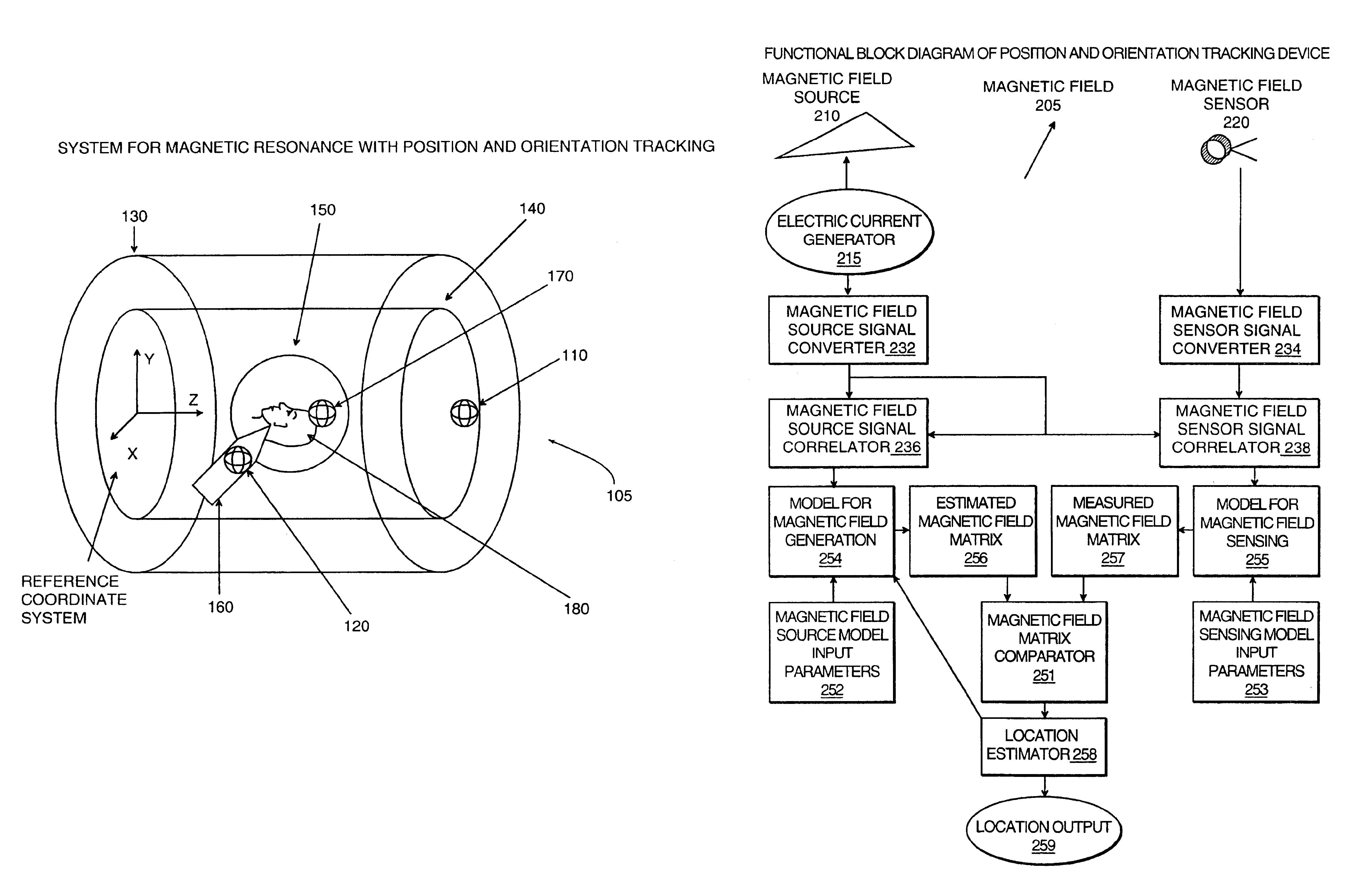
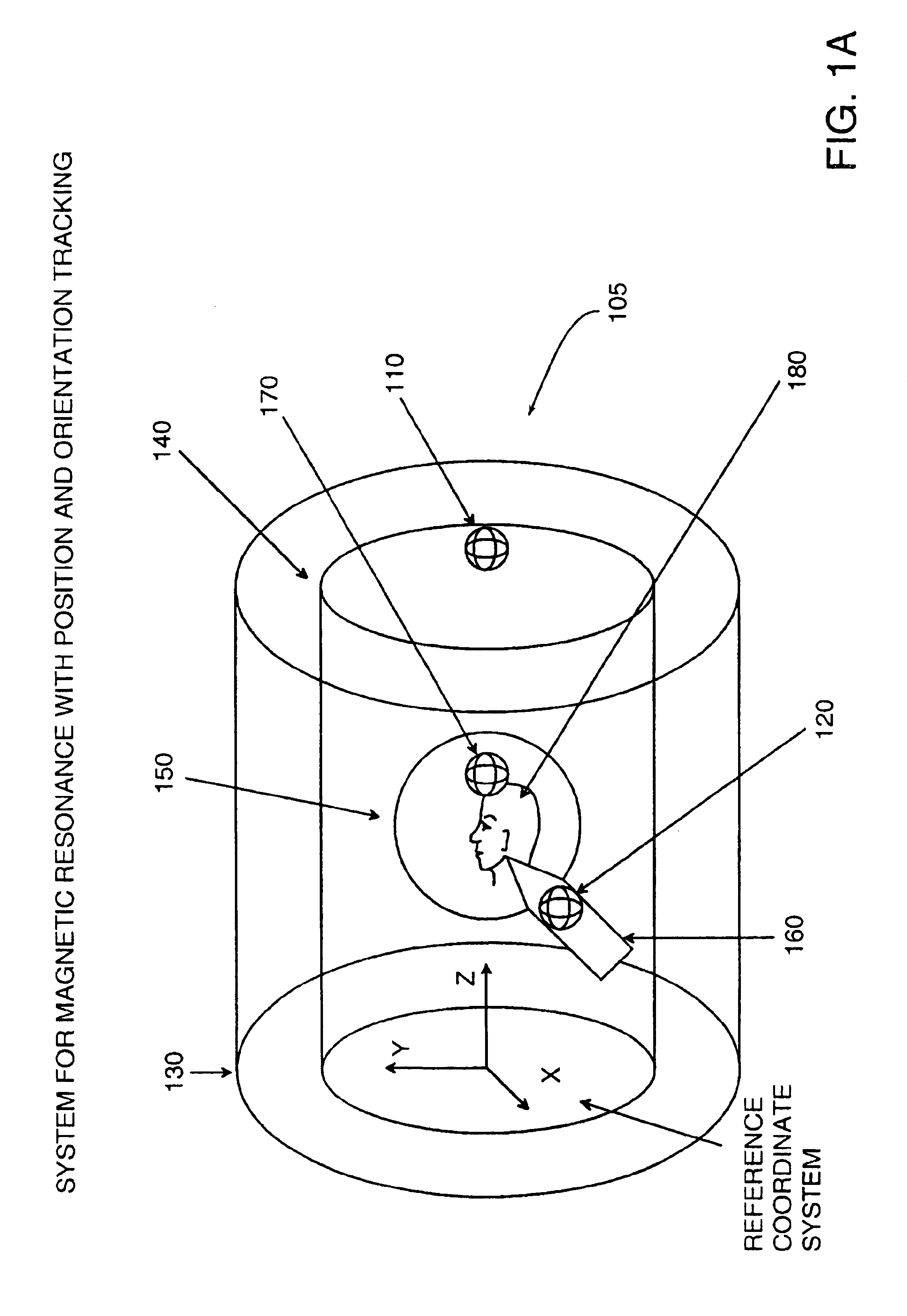
The terms “location” and “position and orientation” will be used interchangeably in the following detailed description and appended claims and shall mean the position of an object, the orientation of an object or both the position and the orientation of an object where one or more degrees of freedom of the object, up to six degrees of freedom in three dimensional space is determined relative to a reference coordinate frame.

The term “coil” in the following description and accompanying claims shall mean a winding or loop of conductive material such as a copper magnet wire through which an electric current can flow. The term “loop” is used in an electrical engineering context referring to a complete circuit for current and does not imply that the shape is necessarily circular.

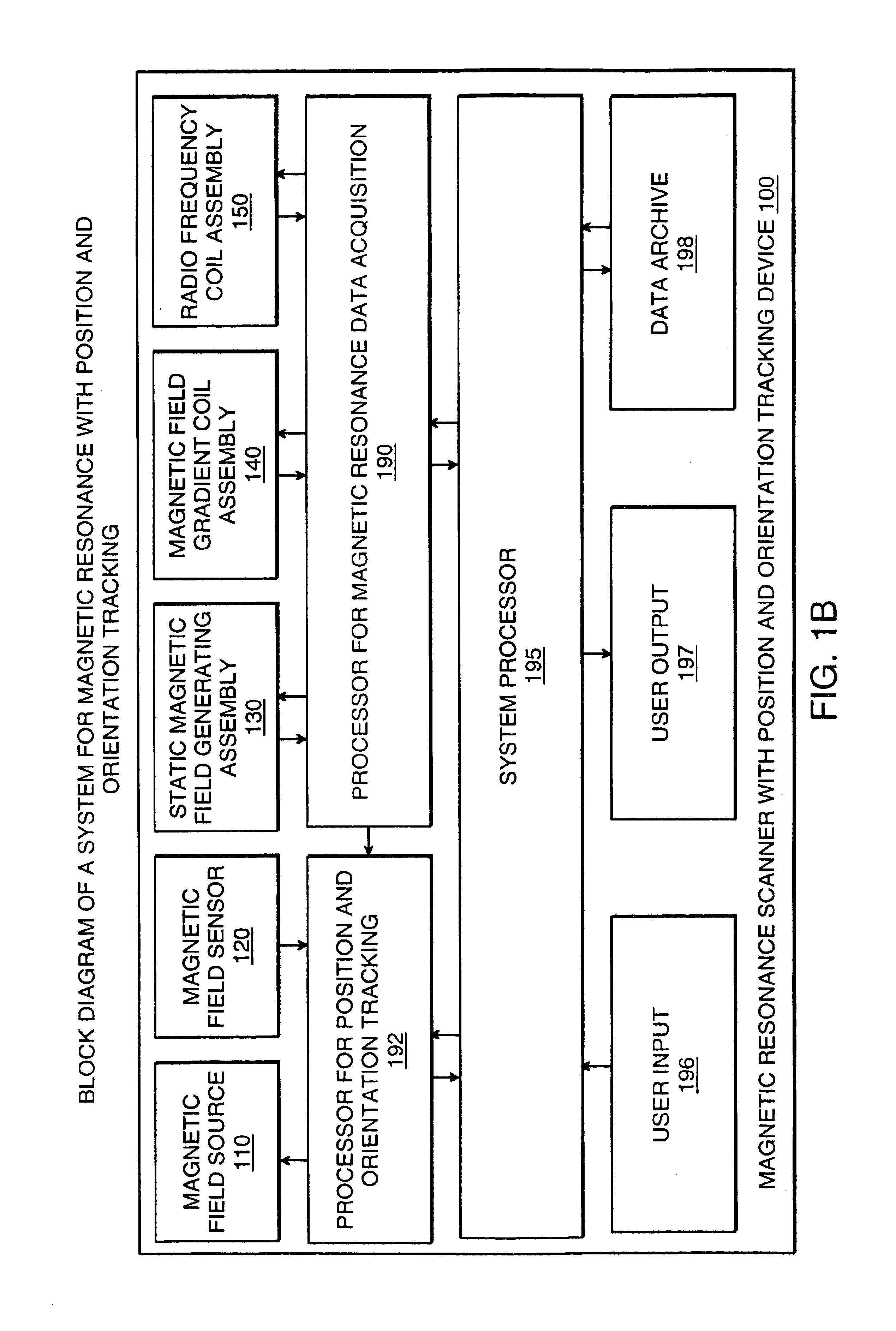
The present invention as embodied in FIG. 1A relates to tracking an object's location relative to a magnetic resonance scanner utilizing electromagnetic fields. Using electromagnetic fields which are independent o...


PUM


Abstract

A system for combining electromagnetic position and orientation tracking with magnetic resonance scanner is provided. One embodiment includes a magnetic resonance scanner defining a reference coordinate system for scanning a target. Coupled to the magnetic resonance scanner is a magnetic field source which produces a magnetic field. The magnetic field is sensed by a magnetic field sensor which produces a signal proportional to the magnetic field. The magnetic field sensor has a location relative to the reference coordinate system. The location of the magnetic field sensor relative to the reference coordinate system of the magnetic resonance scanner is determined by a location tracking device using at least a line segment model of the magnetic field source and the signal from the magnetic field sensor.

Description

TECHNICAL FIELDThe present invention relates to magnetic resonance and position tracking and, more specifically, to the combination of a magnetic resonance scanner with an electromagnetic position and orientation tracking device.BACKGROUND OF THE INVENTIONU.S. Pat. No. 4,737,794 presents a method and apparatus for determining the position of a remote object and its orientation relative to a reference object by measuring the electromagnetic couplings between field generating and sensing elements embedded in reference and remote objects. The apparatus measures the couplings between the fields of the reference and remote object with the generation of a plurality of alternating current (AC) signals applied to the field generating elements and with the measurements of the coupled signals of the sensing elements. The method utilizes a model having an approximation of the dipole magnetic field of the generating source, based on Legendre polynomials, and computes the coupling between the ge...

Claims


Application Information

Patent Timeline
IPC IPC(8): G01R33/28A61B5/055G01R33/38
CPCG01R33/285
Inventor JAKAB, PETER D.
Owner JAKAB PETER D
Why Eureka
Try Eureka