A/D conversion method and apparatus

a conversion method and conversion method technology, applied in pulse manipulation, pulse technique, instruments, etc., can solve the problems of insufficient speed, inability to meet requirements, and inability to achieve the effect of speed

a conversion method and conversion method technology, applied in pulse manipulation, pulse technique, instruments, etc., can solve the problems of insufficient speed, inability to meet requirements, and inability to achieve the effect of speed

US6879278B2Active Publication Date: 2005-04-12DENSO CORP

Image

  • A/D conversion method and apparatus
  • A/D conversion method and apparatus
  • A/D conversion method and apparatus

Examples


Embodiment Construction

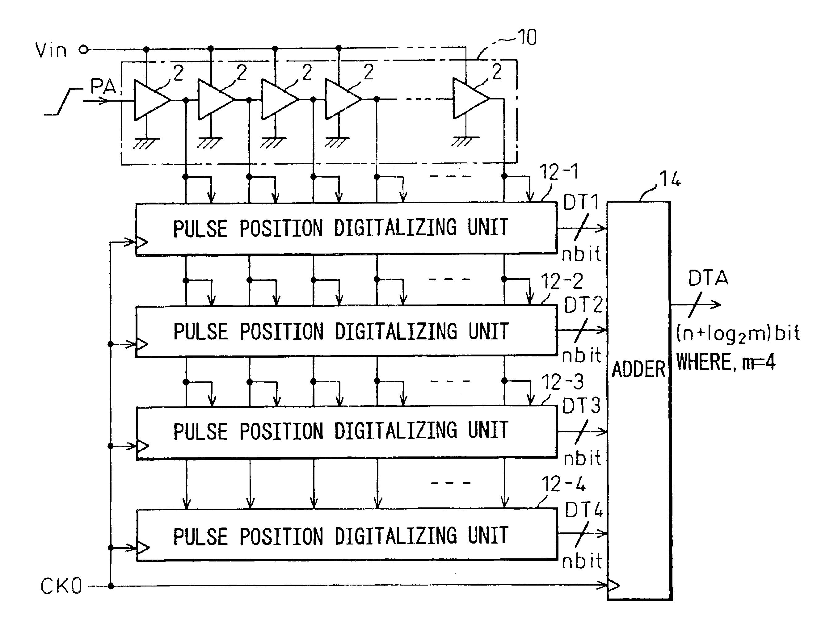
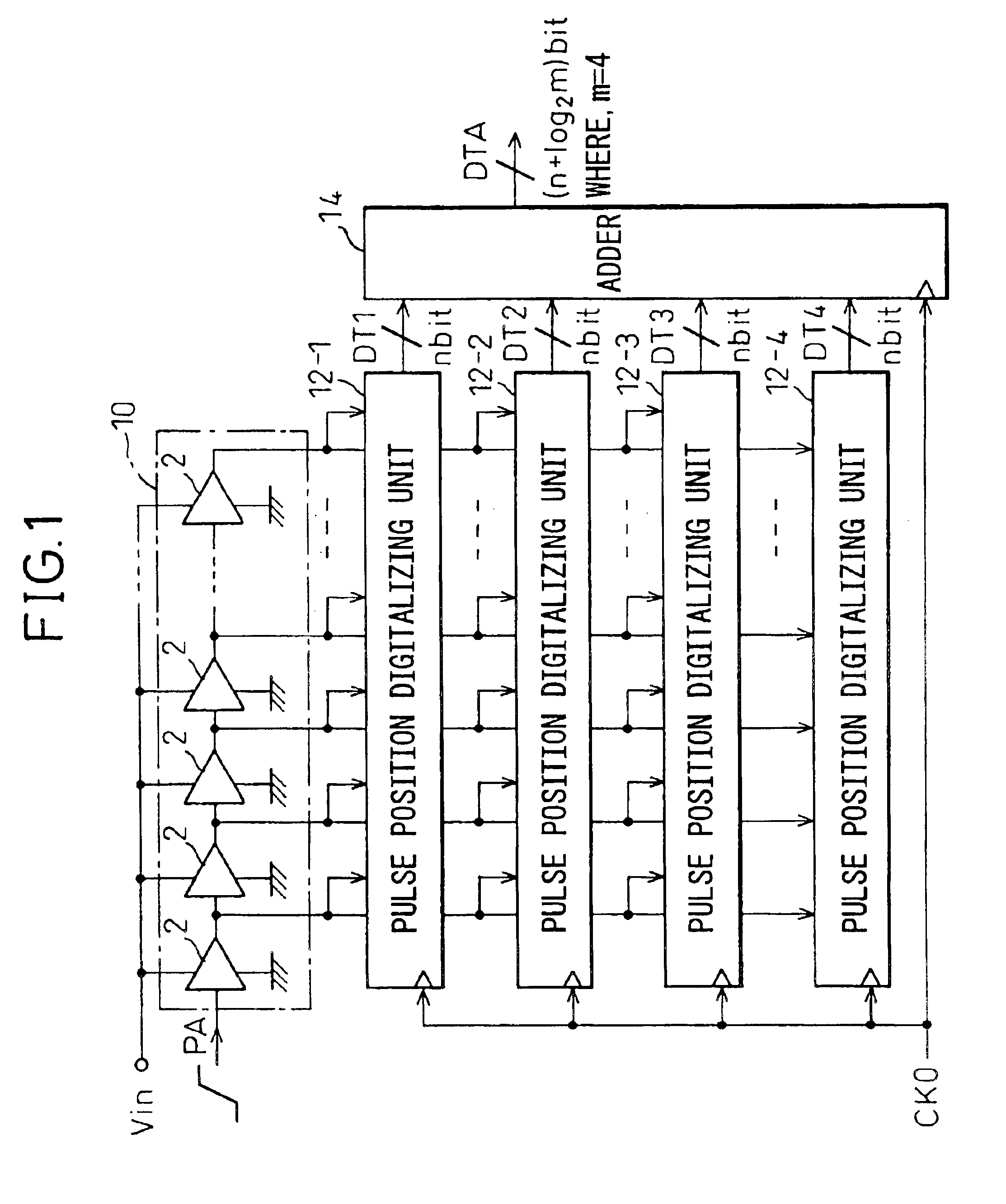
Next, a preferred embodiment of the present invention will be explained with reference to the drawings. FIG. 1 is a block diagram of the configuration of an A / D converter of an embodiment of the present invention.

As shown in FIG. 1, the A / D converter of the embodiment is comprised of a pulse delay circuit 10 comprised of a plurality of series-connected delay units 2 outputting a pulse signal with a delay, m number of (m=4 in the present embodiment) pulse position digitalizing units (corresponding to pulse position digitalizing means of the present invention) 12-1, 12-2, 12-3, and 12-4 for latching output signals from the delay units 2 forming the pulse delay circuit 10 in synchronization with the timings of rising edges (or trailing edges) of a sampling clock CK0 input periodically from the outside and generating n bits of digital data DT1 to DTm by digitalizing the reached positions of the pulse signal PA in the pulse delay circuit 10 from the points of change of the signal levels ...


PUM


Abstract

An A / D converter for driving a plurality of delay units forming a pulse delay circuit by an analog input signal Vin and digitalizing the number of delay units through which a pulse signal passes in the pulse delay circuit at predetermined timings, provided with a plurality of pulse position digitalizing units used for A / D conversion and inputting delay pulses from the delay units of the pulse delay circuit to the pulse position digitalizing units through an inverter group comprised of inverters with different inversion levels (switching threshold level) by different input timings. The digital data obtained by the pulse position digitalizing units are added by an adder.

Description

BACKGROUND OF THE INVENTION1. Field of the InventionThe present invention relates to an A / D conversion method and apparatus for converting an analog input signal to digital data using a pulse delay circuit comprised of a plurality of series-connected delay units outputting a pulse signal with a delay.2. Description of the Related ArtKnown in the past has been, as an A / D converter of a simple configuration giving high resolution digital values, an A / D converter supplying an analog input signal for A / D conversion as power source voltage to a pulse delay circuit comprised of a plurality of delay units comprised of various gate circuits connected in a ring, inputting a pulse signal for propagation to cause the pulse signal to circulate in the pulse delay circuit by a speed corresponding to the delay time of the delay units, and counting the number of delay units through which the pulse signal passes in the pulse delay circuit within a predetermined sampling time during circulation of th...

Claims


Application Information

Patent Timeline
12 Apr 2005
Publication
US6879278B2
IPC
H03K5/135; H03M1/12; H03M1/50; H03M1/60; H03M1/20
CPC
G04F10/005; H03M1/206; H03M1/502
Inventors
WATANABE, TAKAMOTO; TORIGOE, TAKAYUKI