Flow-through rotary damper providing compartment selectivity for a multi-compartment refrigerator

a multi-compartment refrigerator and damper technology, which is applied in the direction of ventilation systems, heating types, domestic cooling apparatus, etc., can solve the problems of unsatisfactory control system type, cost, and inability to control the temperature stability of the freezer, and achieve the effect of increasing the efficiency of fluid flow

Inactive Publication Date: 2005-04-19
ROBERTSHAW CONTROLS CO
View PDF3 Cites 6 Cited by
  • Summary
  • Abstract
  • Description
  • Claims
  • Application Information

AI Technical Summary

Benefits of technology

[0010]In view of the above, the present invention provides a new and improved rotary damper assembly. More particularly, the present invention provides a new and improved rotary damper assembly that provides temperature control for the freezer and multiple fresh food compartments, each of which may be maintained at different temperatures. Further, the present invention provides a new and improved rotary damper assembly that increases the efficiency of fluid flow by providing essentially laminar flow therethrough.
[0011]One feature of the present invention is improved efficiency of fluid transfer through the damper assembly. A further feature of the present invention is selectable and gated operation between a full open and a full closed position to allow variable fluid flow between selected compartments.
[0015]The rotary damper assembly of the present invention provides high efficiency and selectable modulation of fluid flow through the assembly and is highly suitable for use with different electronic flow control applications, including refrigeration equipment. This efficiency is achieved through the dual cylindrical member configuration which provides slew rates which are compatible with gated operation as well as good fluid seal characteristics in the full closed position. Increases in efficiency are realized through the essentially laminar fluid flow through the assembly between the main compartments between which the assembly is installed.

Problems solved by technology

It is generally known that this type of control system is not ideal for temperature stability of the freezer, especially when the outside temperature changes and the fresh food set point temperature is changed.
The principal drawback for such a system is cost.
Further, despite the improved efficiency of this more expensive system, the controlled temperature of both compartments still varies over a substantial range of temperatures.
This is due to the passive nature of both of these control functions, which is characterized by greater operating tolerances as well as limited response time.
Another problem of such a damper system, which also plagues the less expensive systems, is icing of the damper door.
The buildup of ice on the damper door can prevent proper operation of the temperature control.
Such ice buildup may result in the damper door being prohibited from opening or closing, thus upsetting the normal control of temperature in both compartments.
While present models typically allow a user to manually set a damper between the main fresh food compartment and the crisper drawer, such temperature control suffers from the very problems that lead to the use of controlled dampers between the freezer and the fresh food compartment, e.g. wide temperature variances.
This problem is especially acute with the crisper drawer or compartment as its frequency of being opened compared to the main refrigerator door of the fresh food compartment is much less.
As such, the crisper drawer may become over chilled, which may damage vegetables and fruits stored therein.
This results in increased fluid turbulence, which reduces the efficiency of the fluid exchange between the two compartments.

Method used


Image

  • Flow-through rotary damper providing compartment selectivity for a multi-compartment refrigerator
  • Flow-through rotary damper providing compartment selectivity for a multi-compartment refrigerator
  • Flow-through rotary damper providing compartment selectivity for a multi-compartment refrigerator

Examples


Embodiment Construction

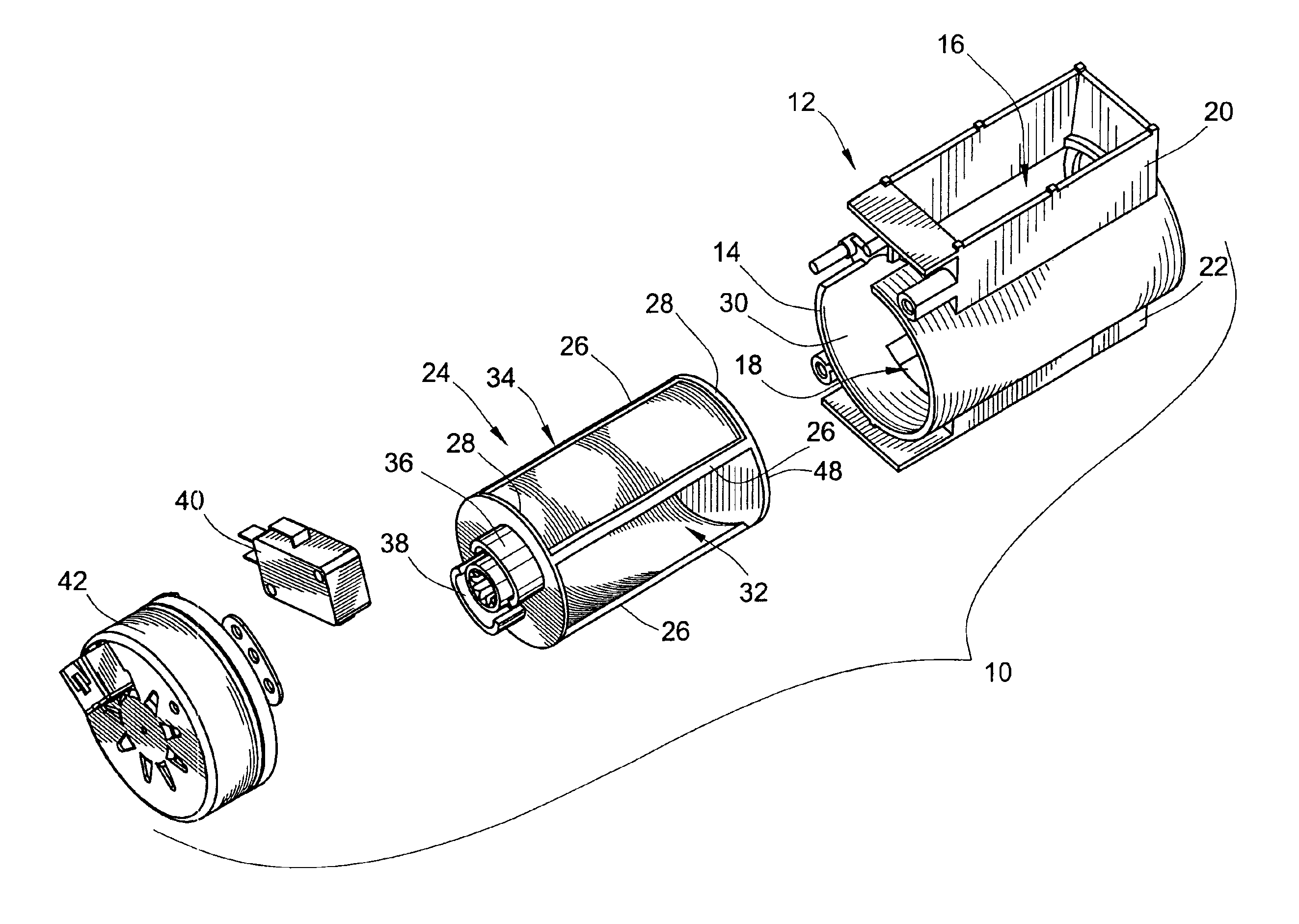
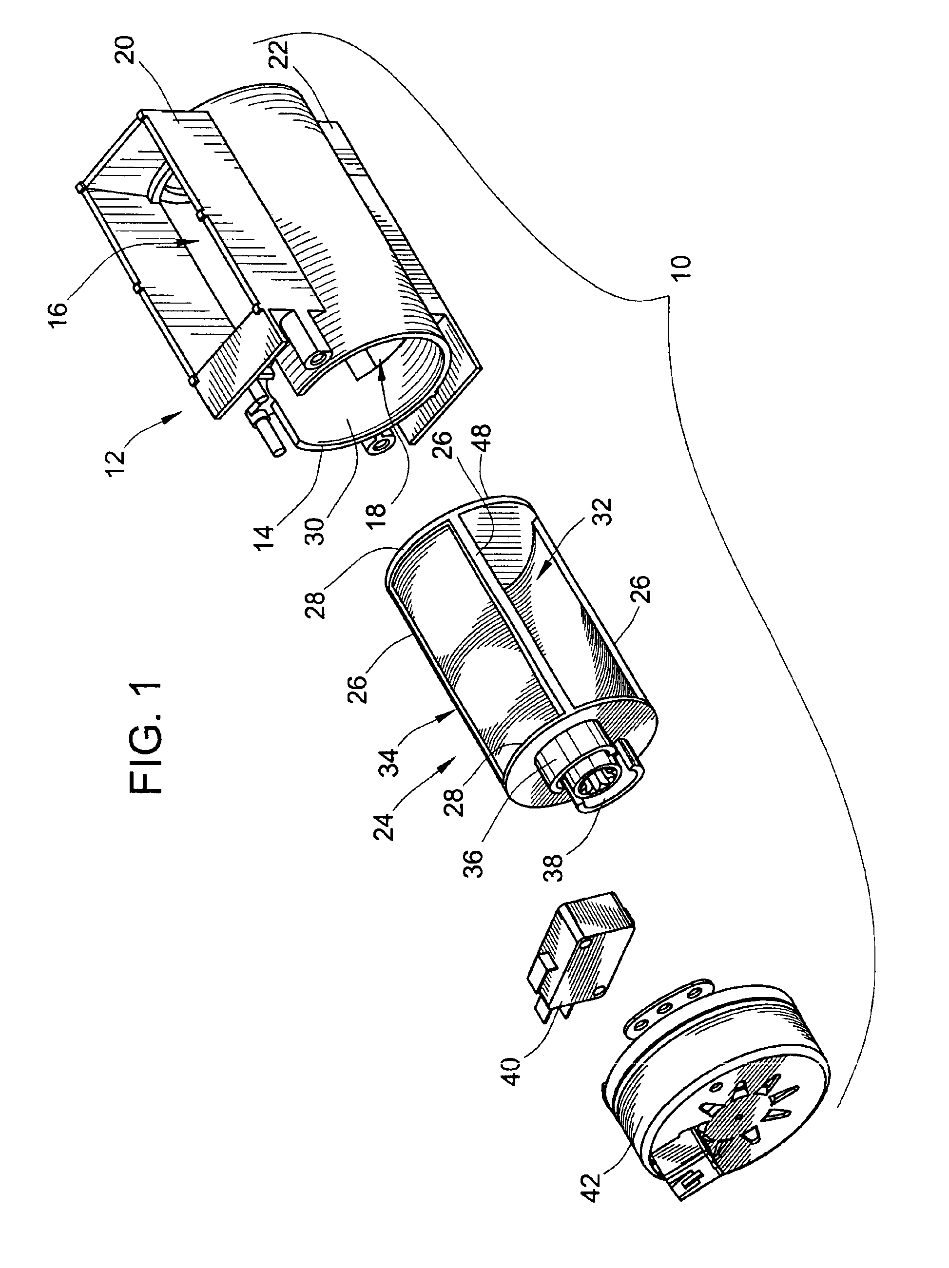
[0030]Turning now to the drawings, an exploded isometric illustration of an embodiment of the flow through rotary damper of the present invention is provided in FIG. 1 to which specific reference is now made. In this embodiment, the rotary damper assembly 10 includes a stationary housing 12. The housing includes a cylindrical outer body member 14 defining inlet and outlet apertures 16, 18 in its outer cylindrical wall. In a preferred embodiment, these two apertures 16, 18 are positioned relative to one another such that fluid flowing into one of the apertures could flow directly out of the other aperture without experiencing a direction of flow change. As will be discussed more fully below, this provides the highest efficiency flow through the rotary damper assembly. However, one skilled in the art will recognize that other installations may necessitate a different orientation of the two apertures 16, 18 relative to one another, such installations experiencing a slightly less effici...


PUM


Abstract

A flow-through rotary damper assembly providing highly efficient, essentially laminar fluid flow therethrough is provided. The rotary damper assembly includes a cylindrical outer body and a cylindrical inner body that are rotatable in relation to one another. The outer body defines apertures in relation to one another to allow fluid flow without requiring fluid direction change. The inner body defines a flow passage having inlet and outlet apertures that may be aligned with the apertures of the outer body to allow fluid flow therethrough, or may be rotated out of alignment to block fluid flow. The outer body includes an aperture on one end to allow fluid flow to a third compartment. The inner body also includes an end aperture that may be aligned therewith. The damper provides selectable fluid flow between each of the compartments depending on the relative position of the cylindrical inner body member.

Description

FIELD OF THE INVENTION[0001]The present invention relates generally to temperature control systems for multi-compartment refrigerators, and more particularly to dampers and damper control systems for regulating the temperature of multi-compartment refrigerators having, e.g. fresh food, crisper, and freezer compartments.BACKGROUND OF THE INVENTION[0002]In a typical multi-compartment refrigerator there are several methods for controlling the temperature of each of the compartments. It is common practice for the refrigeration system, i.e. the compressor, evaporator, fan, etc., to directly cool the freezer compartment. Air from the freezer compartment is directed to the fresh food compartment by means of an opening from the freezer to the fresh food compartment. Air is throttled in this opening by means of some type of air damper control. The damper has traditionally been a manually operated mechanism, which can be adjusted by the user to vary the freezer temperature. The fresh food tem...

Claims


Application Information

Patent Timeline
Patent Type & Authority Patents(United States)
IPC IPC(8): F25D17/04F24F13/10F25D17/06
CPCF24F13/10F25D17/045F25D17/065
Inventor PEARSON, JAMES E.DAVERN, THOMAS J.TUMA, PAUL H.
Owner ROBERTSHAW CONTROLS CO
Why Eureka
Try Eureka