Fuel injection device

a fuel injection device and fuel injection technology, applied in the direction of fuel injection apparatus, machine/engine, feed system, etc., can solve the problem of preventing dirt from being able to collect in the chamber, and achieve the effect of low injection opening pressure, and low pressure boosting ratio

Inactive Publication Date: 2005-04-19
ROBERT BOSCH GMBH
View PDF5 Cites 15 Cited by
  • Summary
  • Abstract
  • Description
  • Claims
  • Application Information

AI Technical Summary

Benefits of technology

[0009]The fuel injection system of the invention has the advantage over the prior art that, as a pressure-controlled device using pressure booster devices with a low pressure boosting ratio, for instance on the order of magnitude of 1:1.5 to 1:3, it achieves relatively low injection opening pressures. A low pressure boosting ratio is advantageous since as a result the installation space for the injector or pressure booster can be kept small; because of the small volumes, highly dynamic pressure buildup and reduction are achieved; depressurization losses are reduced to a minimum; the volumetric flows in the system and the supply quantity of a fuel pump remain low; and the requisite pressure level in the pump and rail, even at high injection pressures of over 2000 bar, remains in the range of up to 1400 bar that has already been mastered by now in mass production. The volumetric flows in the low-pressure system also remain slight. The disposition according to the invention makes it possible also to exploit these advantages for applications in which small fuel quantities must be metered reliably. This is attained by a relief of the closing pressure chamber at precisely the moment when the injection of fuel is to occur. A low boosting ratio can thus be achieved, without causing the opening pressure to assume excessively high values that would make exact metering of small fuel quantities impossible. Moreover, a high closing pressure is assured, which leads to rapid needle closure at high injection pressure. It is especially advantageous that at least the fuel pressure of the high-pressure fuel source can prevail constantly (aside from pressure fluctuations occurring in the system) in the high-pressure chamber. This advantageously assures that at the very first moment when the injector opens, a high injection pressure prevails at the injection openings, and fuel can be metered to the combustion chambers in exact dosages within small time slots. Furthermore, the design of the pressure booster can be made simple and sturdy, since besides the low-pressure system, there is only one further fuel system with higher fuel pressure.
[0010]If the function of the pressure chamber of the injector is taken on by the high-pressure chamber of the pressure booster device, the result is a reduced idle volume downstream of the pressure booster device that still has to be compressed to high pressure. Moreover, the amplitude of any fluctuations that occur between the closing pressure chamber and the pressure chamber is lessened, since a shorter flow connection from the closing pressure chamber to the pressure chamber results. The overall result is a more-reliable mode of operation, with the capability of faster switching.
[0011]In a further advantageous embodiment with a diametrically opposed disposition of the line orifices into the chambers of the pressure booster device and / or of the closing pressure chamber, it can be attained that there is a constant flow through the chambers during operation. Especially at small injection quantities, it is thus also assured that the chambers have a flow through them continuously. As a result, local overheating of the fuel in the chambers from constant compression and depressurization can be avoided, along with component damage. Moreover, this prevents dirt from being able to collect in the chambers.

Problems solved by technology

Moreover, this prevents dirt from being able to collect in the chambers.

Method used


Image

  • Fuel injection device
  • Fuel injection device
  • Fuel injection device

Examples


Embodiment Construction

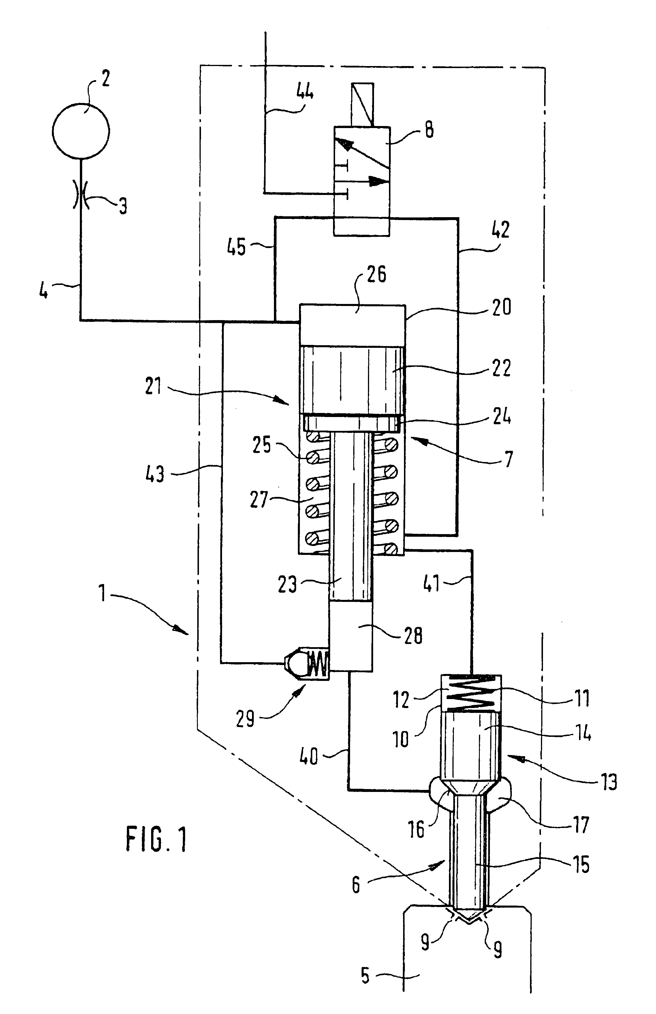
[0023]In FIG. 1, a fuel injection system is shown in which a fuel injector 1 that has a pressure booster device 7 communicates with a high-pressure fuel source 2 via a fuel line 4 that is provided with a throttle 3. The high-pressure fuel source includes a plurality of elements not shown in detail, such as a fuel tank, a pump, and the high-pressure rail of a common rail system known per se; the pump furnishes a fuel pressure of up to 1600 bar to the high-pressure rail by pumping fuel from the tank into the high-pressure rail. A separate injector supplied from the high-pressure rail is provided for each cylinder of the engine. The injector 1 shown as an example in FIG. 1 has a fuel injection valve 6, with a closing piston 13 that with its injection openings 9 protrudes into the combustion chamber 5 of a cylinder of an internal combustion engine. The closing piston 13 is surrounded at a pressure shoulder 16 by a pressure chamber 17, which communicates with the high-pressure chamber 28...


PUM


Abstract

A fuel injection system for internal combustion engines includes an injector supplied from a high-pressure fuel source and with a pressure booster device, in which the closing piston can be acted upon by fuel pressure to attain a force exerted on the closing piston in the closing direction, and in which the closing pressure chamber and the return chamber of the pressure booster device are formed by a common closing pressure return chamber, and all the portions of the closing pressure return chamber communicate with one another permanently for exchanging fuel, so that despite a low pressure boost by the pressure booster device, a relatively low injection opening pressure is attainable.

Description

CROSS-REFERENCE TO RELATED APPLICATIONS[0001]This application is a 35 USC 371 application of PCT / DE 02 / 01550 filed on Apr. 27, 2002.BACKGROUND OF THE INVENTION[0002]1. Field of the Invention[0003]The invention is directed to an improved fuel injection system for internal combustion engines, including a pressure booster between the fuel injector and a high pressure fuel source.[0004]2. Description of the Prior Art[0005]From German Patent Disclosure DE 43 11 627, fuel injection systems are already known in which an integrated pressure booster piston, by means of filling or evacuating a return chamber, makes it possible to increase the fuel injection pressure above the value furnished by a common rail system.[0006]From U.S. Pat. No. 6,113,000, an injection system is known that has a high-pressure reservoir and a medium-pressure reservoir; the high-pressure reservoir can selectively also be filled with fuel.[0007]German Patent Disclosure DE 199 10 970 describes fuel injection systems wi...

Claims


Application Information

Patent Timeline
Patent Type & Authority Patents(United States)
IPC IPC(8): F02M57/00F02M57/02F02M59/00F02M59/46F02M59/10F02M47/02F02M63/00
CPCF02M47/027F02M57/025F02M63/0026F02M63/0045F02M59/105F02M2200/21
Inventor MAGEL, HANS-CHRISTOPH
Owner ROBERT BOSCH GMBH
Why Eureka
Try Eureka