Method of retrofitting an unitized injector for ultrasonically stimulated operation

a unitized, injector technology, applied in the direction of fuel injecting pumps, combustion air/fuel air treatment, machines/engines, etc., can solve the problems of lubricity problems, adversely affecting the amount of fuel that is able to enter the combustion chamber, and the need to use exotic metals, so as to increase the fuel velocity

Inactive Publication Date: 2005-04-19
KIMBERLY-CLARK WORLDWIDE INC
View PDF144 Cites 25 Cited by
  • Summary
  • Abstract
  • Description
  • Claims
  • Application Information

AI Technical Summary

Benefits of technology

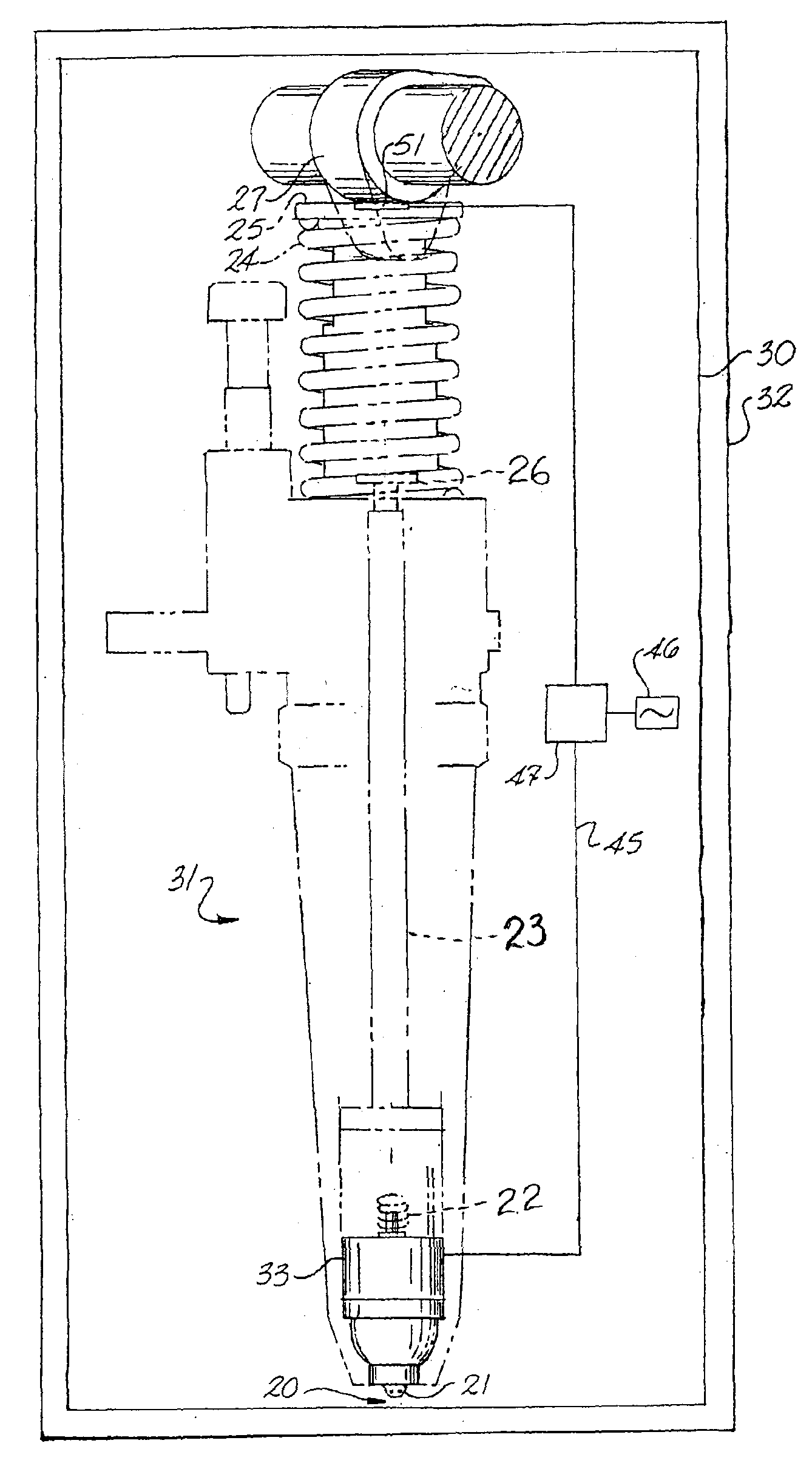
[0013]The exterior of the wall is surrounded by a coil that is capable of inducing a changing magnetic field in the region occupied by the magnetostrictive portion and thus causing the magnetostrictive portion to vibrate at ultrasonic frequencies. This vibration causes the tip of the needle, which is disposed in the liquid fuel near the entrance to the discharge plenum and the channels leading to the injector's exit orifices, to vibrate at ultrasonic frequencies and therefore subjects the fuel to these ultrasonic vibrations. The ultrasonic stimulation of the fuel as it leaves the exit orifices permits the injector to achieve the desired performance while operating at lower pressures and larger exit orifices than the conventional solutions that are aimed at increasing the velocity of the fuel exiting the injector.

Problems solved by technology

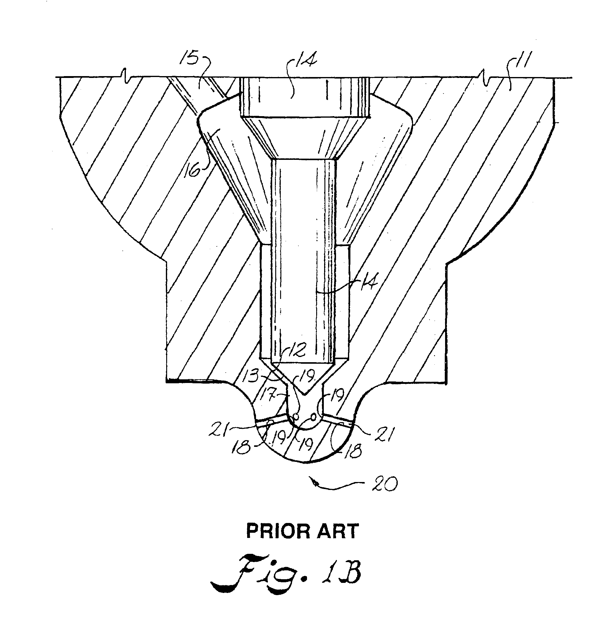
However, the injector's exit orifices can become fouled and thereby adversely affect the amount of fuel that is able to enter the combustion chamber.
However, these solutions introduce problems of their own such as: the need to use exotic metals; lubricity problems; the need to micro inch finish moving parts; the need to contour internal fuel passages; high cost; and direct injection.
For example, the reliance on smaller orifices means that the orifices are more easily fouled.
Such exotic metals increase the cost of the injector.
The higher pressures also create lubricity problems that cannot be solved by relying on additives in the fuel for lubrication of the injector's moving parts.
Other means of lubricity such as applying a micro inch finish on the moving metal parts is required at great expense.
Such higher pressures also create wear problems in the internal passages of the injector that must be counteracted by contouring the passages, which requires machining that is costly to perform.
These wear problems also erode the exit orifices, and such erosion changes the character of the injector's plume over time and affects performance.
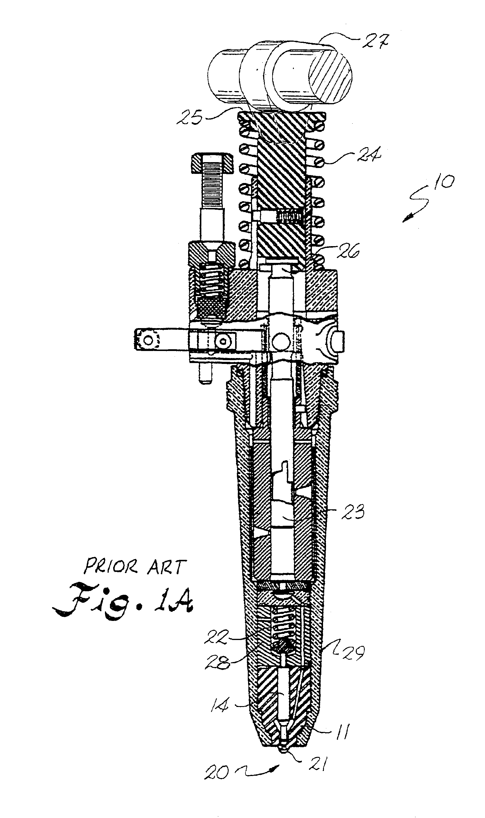
However, unitized fuel injectors cannot be fitted with such ultrasonic transducers because of the disposition of the fuel pump, cam follower and overhead cam in axial alignment with the needle.
This vibration causes the tip of the needle, which is disposed in the liquid fuel near the entrance to the discharge plenum and the channels leading to the injector's exit orifices, to vibrate at ultrasonic frequencies and therefore subjects the fuel to these ultrasonic vibrations.

Method used


Image

  • Method of retrofitting an unitized injector for ultrasonically stimulated operation
  • Method of retrofitting an unitized injector for ultrasonically stimulated operation
  • Method of retrofitting an unitized injector for ultrasonically stimulated operation

Examples


Embodiment Construction

[0022]Reference now will be made in detail to the presently preferred embodiments of the invention, one or more examples of which are illustrated in the accompanying drawings. Each example is provided by way of explanation of the invention, not limitation of the invention. In fact, it will be apparent to those skilled in the art that various modifications and variations can be made in the present invention without departing from the scope or spirit of the invention. For instance, features illustrated or described as part of one embodiment, can be used on another embodiment to yield a still further embodiment. Thus, it is intended that the present invention cover such modifications and variations as come within the scope of the appended claims and their equivalents. The same numerals are assigned to the same components throughout the drawings and description.

[0023]As used herein, the term “liquid” refers to an amorphous (noncrystalline) form of matter intermediate between gases and s...


PUM


Abstract

A method involves retrofitting conventional injectors with needles having magnetostrictive portions and wound coils configured and disposed so as to subject the magnetostrictive portions of the needles to ultrasonically oscillating magnetic fields.

Description

PRIORITY CLAIM[0001]The present application hereby claims priority based on and is a division of U.S. patent application Ser. No. 09 / 916,092, which was filed on Jul. 26, 2001, now U.S. Pat. No. 6,663,027 and claims the benefit of Provisional Application No. 60 / 254,683, filed Dec. 11, 2000 and is hereby incorporated herein by this reference.RELATED APPLICATIONS[0002]This application is one of a group of commonly assigned patent applications which include application Ser. No. 08 / 576,543 entitled “An Apparatus and Method for Emulsifying A Pressurized Multi-Component Liquid”, in the name of L. K. Jameson et al.; and application Ser. No. 08 / 576,522 entitled “Ultrasonic Liquid Fuel Injection Apparatus and Method”, in the name of L. H. Gipson et al. The subject matter of each of these applications is hereby incorporated herein by this reference.BACKGROUND OF THE INVENTION[0003]The present invention relates to an apparatus and method for injecting fuel into a combustion chamber and in parti...

Claims


Application Information

Patent Timeline
Patent Type & Authority Patents(United States)
IPC IPC(8): F02M61/16F02M61/18F02M57/00F02M57/02F02M61/00F02M69/04F02M51/06F02M63/00
CPCF02M57/023F02M61/16F02M61/166F02M61/18F02M69/041F02M61/168F02M2200/9007F02M2200/24F02M27/08
Inventor JAMESON, LEE KIRBYCOHEN, BERNARDGIPSON, LAMAR HEATH
Owner KIMBERLY-CLARK WORLDWIDE INC
Why Eureka
Try Eureka