

Temperature sensor and production method thereof
- Summary
- Abstract
- Description
- Claims
- Application Information
AI Technical Summary
Benefits of technology
Problems solved by technology
Method used
Image

Examples
Embodiment Construction
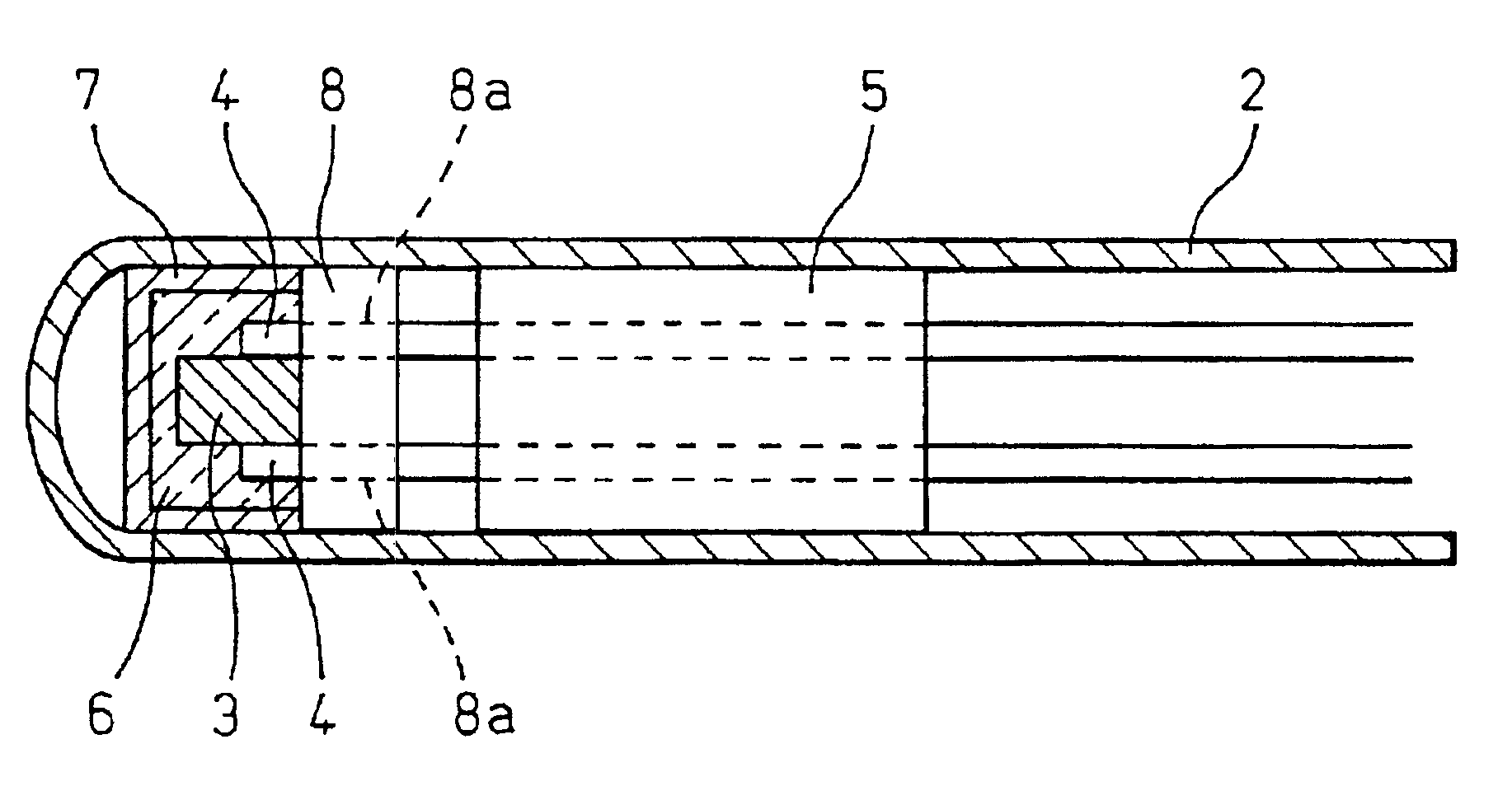
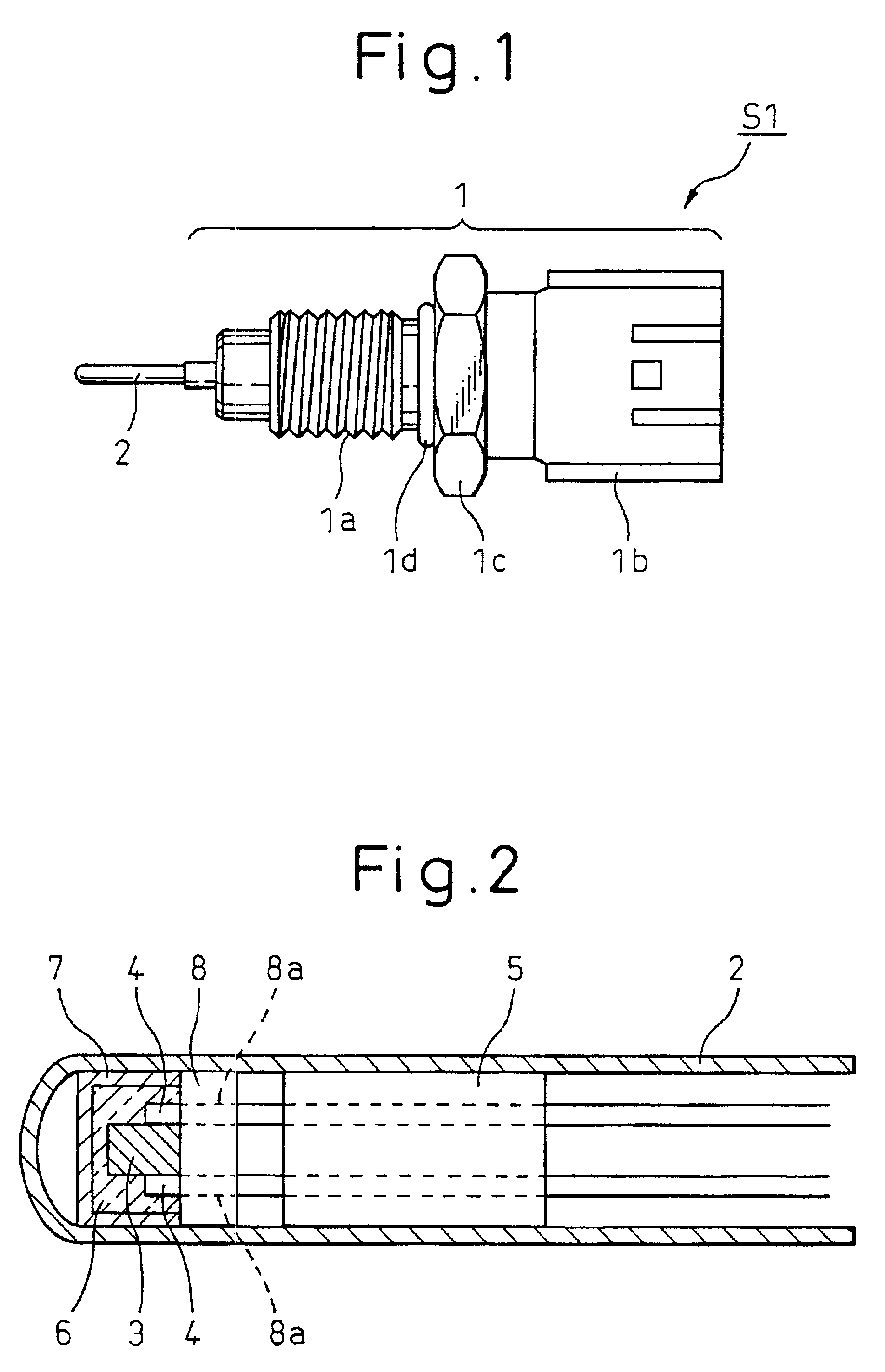
[0024]The invention will be hereinafter explained using the several preferred embodiments shown in the accompanying drawings. FIG. 1 is an appearance view showing an overall construction of a temperature sensor S1 according to one embodiment of the invention. FIG. 2 is an enlarged view showing a sectional structure inside a metal cover (metal pipe) 2 that constitutes a temperature sensitive portion in FIG. 1. This temperature sensor S1 can be applied to an exhaust gas temperature sensor used in a high temperature environment of at least 500° C., for example.
[0025]Referring to FIG. 1, reference numeral 1 denotes a housing having a shape of a stepped cylinder. The housing 1 is made of a metal material (such as a stainless steel) having high heat resistance. A screw portion 1a, capable of screw coupling with a fitting hole of a member such as an exhaust pipe, is formed on an outer peripheral surface of the housing 1 at one of its ends. A connector portion 1b to be connected to wiring m...
PUM
 Abstract
Description
Claims
Application Information