Remediation of soil piles using central equipment

a technology of soil piles and central equipment, applied in the direction of lighting and heating apparatus, combustion types, nuclear engineering, etc., can solve the problems of soil contamination, soil contamination, chemical, biological and/or radioactive compounds,

Inactive Publication Date: 2005-04-19
TERRATHERM
View PDF57 Cites 39 Cited by
  • Summary
  • Abstract
  • Description
  • Claims
  • Application Information

AI Technical Summary

Benefits of technology

[0030]In a soil remediation embodiment, contaminated soil may be transported to a location for remediation. Two or more treatment sites may be proximate each other at the location. One or more barriers may form at least a partial border for containing soil within the treatment sites. In an embodiment, a barrier forming a border for a treatment site may include connectors for coupling heater elements to shared equipment. Shared equipment at the location may be used at more than one treatment site. Shared equipment may include, for example, a power source and / or a vacuum source. In an embodiment, shared equipment may be used concurrently or successively at two or more treatment sites at the location. Remediation at the treatment sites may be coordinated such that shared equipment in a central treatment facility operates substantially continuously.

Problems solved by technology

Soil contamination is a matter of concern in many locations.
Soil may be contaminated with chemical, biological, and / or radioactive compounds.
Contamination of soil may occur in a variety of ways, such as material spillage, leakage from storage vessels, and landfill seepage.
Public health concerns may arise if contaminants migrate into aquifers or into air.
Vapors removed from the soil by the vacuum may include contaminants from the soil.
Heat added to contaminated soil may raise a temperature of the soil above vaporization temperatures of soil contaminants.
If soil temperature exceeds a vaporization temperature of a soil contaminant, the contaminant may vaporize.
Heat applied to the soil may also result in the destruction of contaminants in situ.
A significant portion of contaminants within the air and vapor may be destroyed by pyrolysis and / or oxidation when the air and vapor passes through high temperature zones surrounding and in heater / vapor extraction wells.
In other well pattern embodiments, spacing of the wells may result in non-regular polygonal well patterns.
The use of metal pipe may make a cost of a collection system expensive.
Installation of a metal pipe collection system may be labor and time intensive.
The barrier may limit the amount of air and water drawn into the treatment area from the surroundings.

Method used


Image

  • Remediation of soil piles using central equipment
  • Remediation of soil piles using central equipment
  • Remediation of soil piles using central equipment

Examples


Embodiment Construction

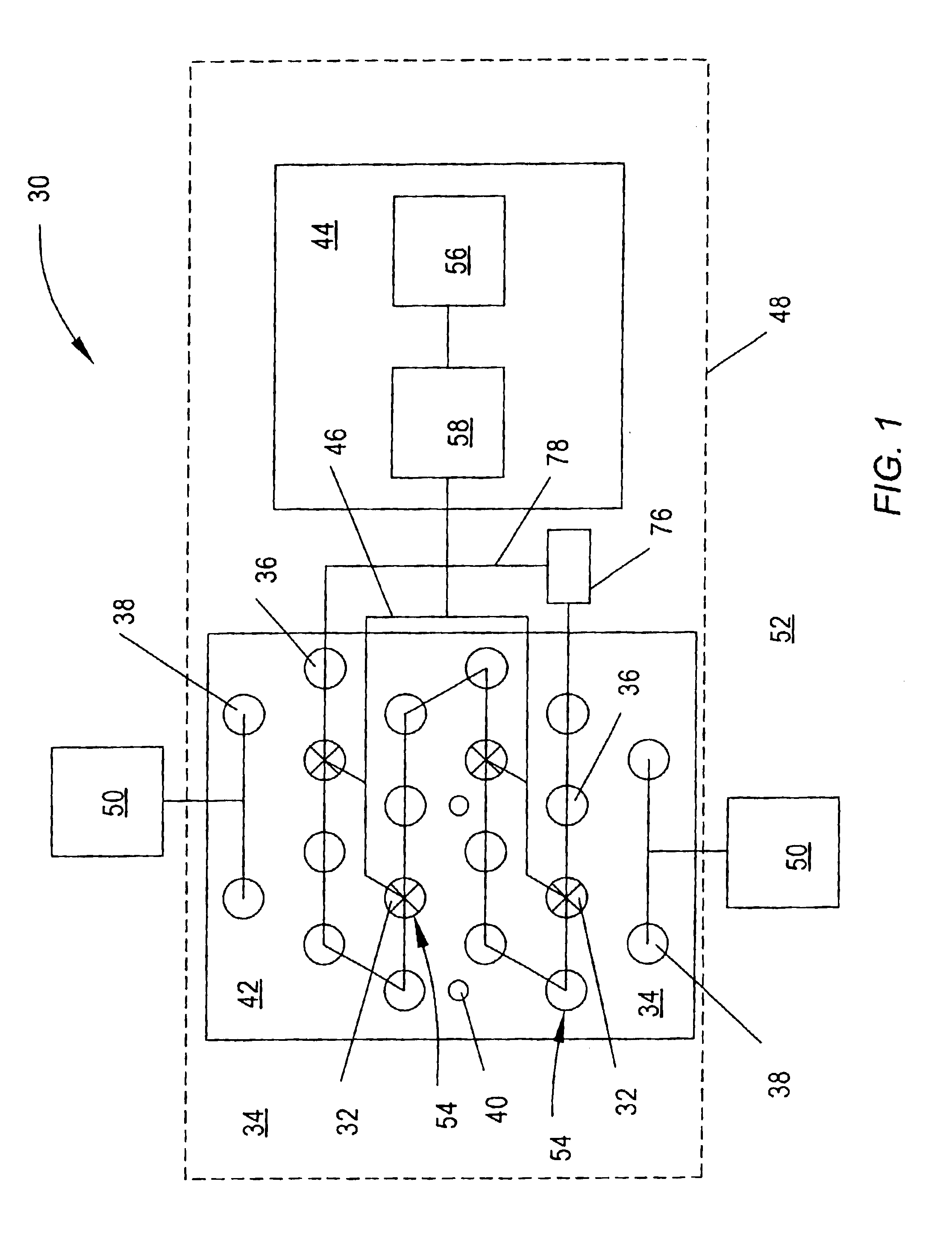
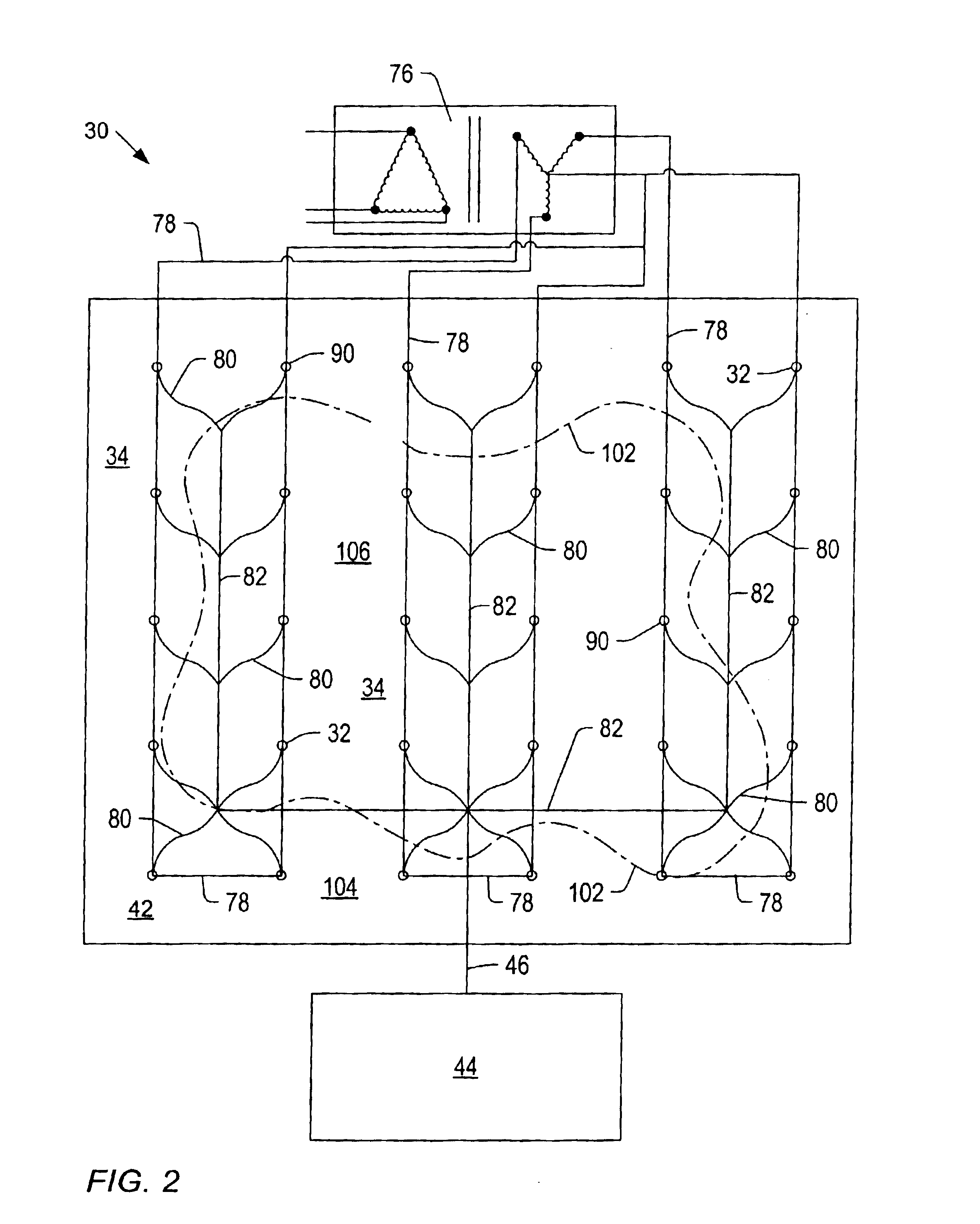
[0054]A soil remediation system may remove or reduce contaminants within a selected soil region. FIGS. 1 and 2 show schematic representations of embodiments of soil remediation systems 30. Soil remediation system 30 depicted in FIG. 1 may include one or more extraction wells 32 within soil 34. Soil remediation system 30 may optionally include one or more heat injection wells 36, one or more fluid injection wells 38, and one or more test wells 40. Fluid injection wells 38 and / or test wells 40 may be located inside or outside of a pattern of extraction wells 32 and heat injection wells 36. Extraction wells 32, heat injection wells 36, fluid injection wells 38, and / or test wells 40 may include well casings. Portions of the well casings may be perforated to allow fluid to pass into or out of the well casings. Alternatively, extraction wells 32, heat injection wells 36, fluid injection wells 38, and / or test wells 40 may include a cased portion and an uncased portion. The uncased portion ...


PUM


Abstract

Methods are provided for remediating contaminated soil. The methods may include collecting contaminated soil at a plurality of treatment sites. The contaminated soil at one or more of the plurality of treatment sites may be at least partially contained. Contaminated soil at the plurality of treatment sites may be treated with equipment in a central treatment facility. Treatment of the plurality of sites may be coordinated such that equipment in the central treatment facility operates substantially continuously as soil is delivered to, treated at, and removed from various treatment sites. The plurality of sites may be treated in a sequential manner, in which soil is delivered to one site, treated at a second site, and removed from a third site substantially simultaneously.

Description

BACKGROUND[0001]1. Field of the Invention[0002]The present invention generally relates to soil remediation systems and methods. Embodiments of the invention relate to systems and methods of treating soil at a plurality of sites substantially continuously using equipment in a central treatment facility.[0003]2. Description of Related Art[0004]Soil contamination is a matter of concern in many locations. “Soil” refers to unconsolidated and consolidated material in the ground. Soil may include natural formation material such as dirt, sand, and rock, as well as fill material. Soil may be contaminated with chemical, biological, and / or radioactive compounds. Contamination of soil may occur in a variety of ways, such as material spillage, leakage from storage vessels, and landfill seepage. Public health concerns may arise if contaminants migrate into aquifers or into air. Soil contaminants may also migrate into the food supply through bioaccumulation in various species in a food chain.[0005...

Claims


Application Information

Patent Timeline
Patent Type & Authority Patents(United States)
IPC IPC(8): B09C1/02B09C1/10B09C1/08B09C1/00B09C1/06E02D3/11E02D3/00
CPCB09C1/00B09C1/005B09C1/02E02D3/11B09C1/08B09C1/10B09C1/06
Inventor STEGEMEIER, GEORGE L.VINEGAR, HAROLD J.BAKER, RALPH S.BIERSCHENK, JOHN M
Owner TERRATHERM
Why Eureka
Try Eureka