Remote distribution cabinet

a remote distribution and cabinet technology, applied in the direction of cabinet/cabinet/drawer, electrical apparatus casing/cabinet/drawer, coupling device connection, etc., can solve the problems of large number of power distribution enclosures, large area, and large area of devices, so as to simplify and reduce the construction cost of the remote distribution cabinet. , the effect of small area

Inactive Publication Date: 2005-04-19
VERTIV CORP
View PDF32 Cites 73 Cited by
  • Summary
  • Abstract
  • Description
  • Claims
  • Application Information

AI Technical Summary

Benefits of technology

[0004]The present invention is directed to a remote distribution cabinet, which overcomes the design and installation limitations of prior art power distribution enclosures. In one embodiment of the present invention, the remote distribution cabinet uses structural members and internal panelboard components as the frame assembly. This design contains fewer structural components than prior art designs, and thereby allows the remote distribution center to house, for example, 168 branch circuit devices (the equivalent of four full panelboards) in a relatively small area. Moreover, having fewer structural components requires less welding during assembly resulting in simplified and less costly remote distribution cabinet construction.
[0005]Unlike prior art remote distribution cabinets, a remote distribution cabinet in accordance with the present invention includes no isolation transformer, which helps to minimize the space required by the remote distribution cabinet. By separating the transformer from the panelboard function, a remote distribution cabinet in accordance with the present invention may be extremely compact, so that it will fit within the area of a standard 24-inch raised-floor tile while still permitting removal of adjacent floor tiles.
[0007]In one embodiment, the remote distribution cabinet is designed to fit into the space of a standard 2 ft.×2 ft. (600 mm×600 mm) raised floor tile, which allows adjacent tiles to be removed without disturbing the enclosure. In this design, the bottom member of the remote distribution cabinet can replace the raised floor tile. Moreover, the bottom member includes a void space, eliminating the need to cut raised floor tiles for cable entry. In addition, the remote distribution cabinet design eliminates tripping hazards created by gap spaces in the raised floor caused by users removing entire tiles to set the enclosure on the structural floor beneath. Further, the remote distribution cabinet may include a junction box that is beneath the floor and attached to the remote distribution cabinet bottom member, thereby allowing users to terminate input and output cables in the junction box for a more efficient installation.
[0008]Despite its small size, a remote distribution cabinet in accordance with the present invention, has increased accessibility. Accessibility is provided by the use of inline 42-pole panelboards with wide access channels. Up to four panelboards are separated into vertical compartments with individual hinged access covers. Any compartment can be serviced without exposing the wiring of the other three panelboards.
[0010]The remote distribution cabinet may also feature clear insert panels to allow inspection of the circuit breakers without opening the cabinet, tie breakers to allow the internal panelboards to be connected to different inputs, and adjustable access panels to compensate for breaker creep.

Problems solved by technology

These devices are smaller than the predecessors, more numerous, densely packed and consume less power.
As is evident, this requires additional space, expending the space available for additional electrical equipment and / or electronic components.
Available power distribution enclosures have a number of disadvantages that are particularly noticeable when a single enclosure having a large number of branch circuits is required.
Prior art power distribution enclosures having a large number of branch circuits typically comprise frame structural cabinet and post members in addition to panel frame members that increase the size of the enclosure and limit the space avaiable for branch circuit panelboards.
Such enclosures may also require the entire raised floor tile be removed and the enclosure set on the structural floor beneath causing a gapped space in the raised floor.
Conversely, if the enclosure is too large it overlaps to adjacent tiles causing the inability to remove the adjacent tiles if needed.
Yet another limitation of prior art designs is the lack of ability for users to have neat, easily accessible, and efficient installations because of numerous wires that extend from the enclosure branch circuits to the space under the raised floor.

Method used


Image

  • Remote distribution cabinet
  • Remote distribution cabinet
  • Remote distribution cabinet

Examples


Embodiment Construction

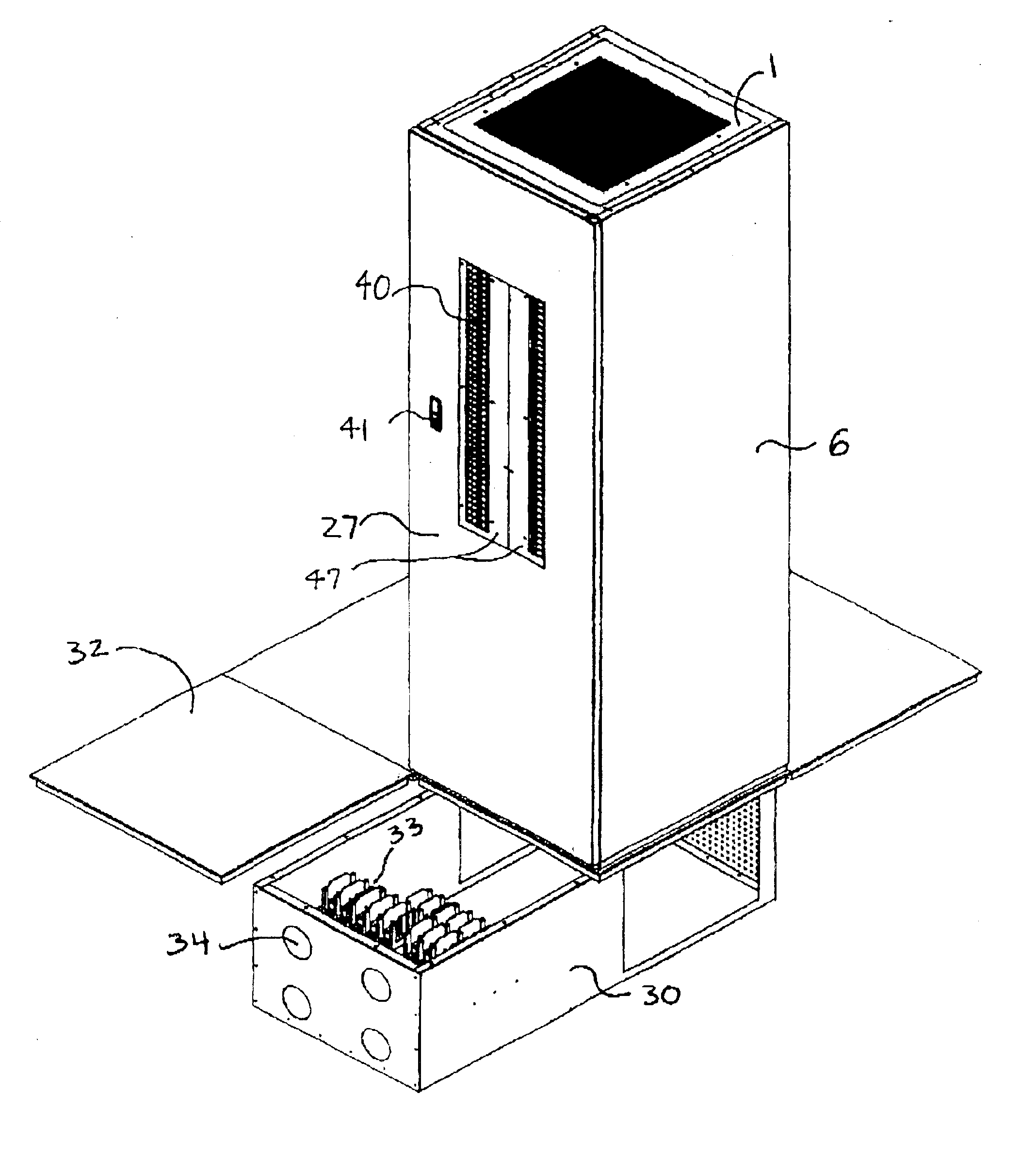
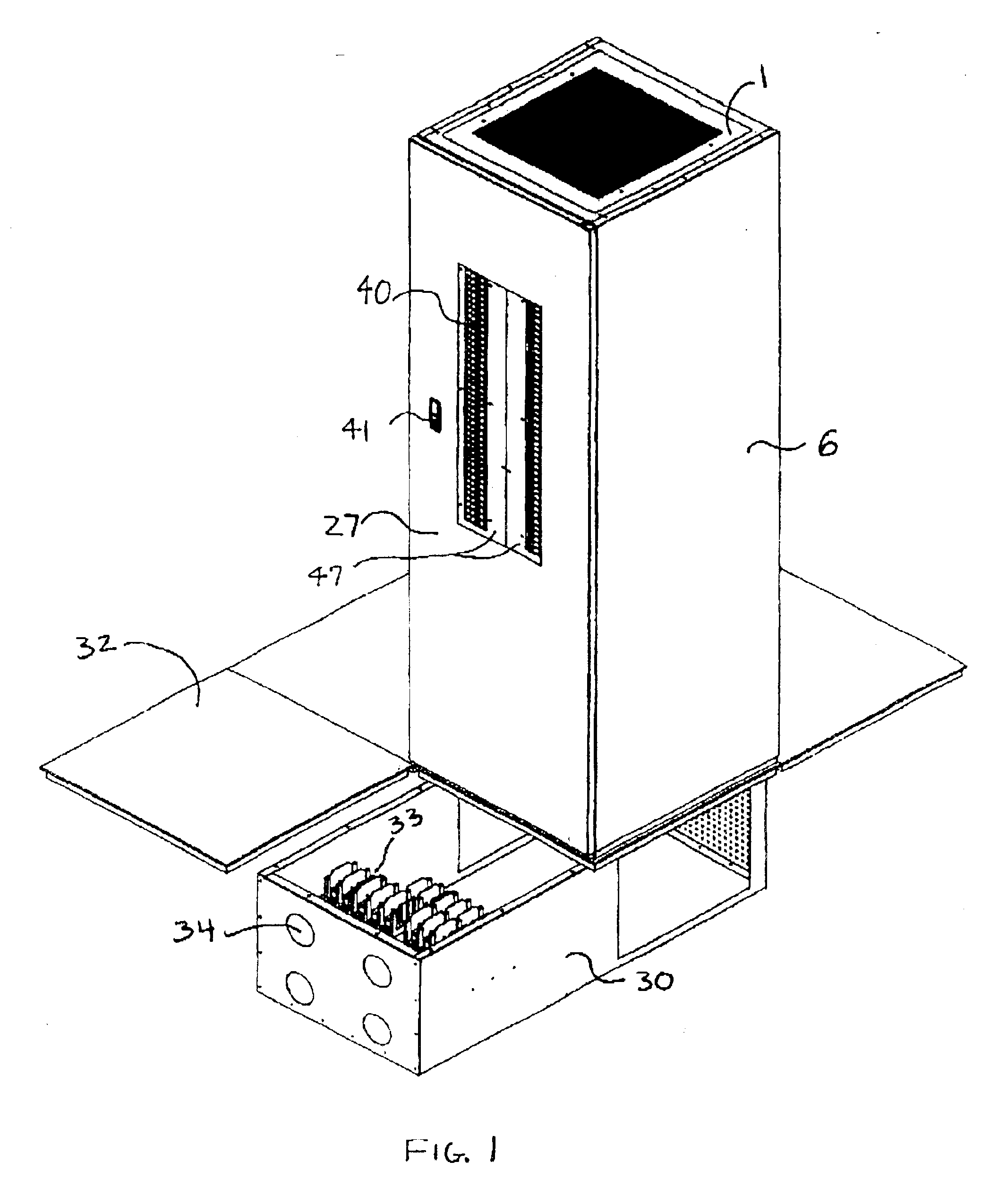
[0026]The outer portion of a remote distribution cabinet in accordance with the present invention is illustrated in FIG. 1. The remote distribution cabinet includes a door 27, door latch 41, side member cover 6, a screened protective top 1, and a doubled-tile size junction box 30 beneath the raised floor 32 and attached to the bottom member (see FIG. 2) of the remote distribution cabinet. Also illustrated in FIG. 1 are a number of branch circuit breakers 40. As shown, these circuit breakers 40 are operable without the need to open the enclosure door 27. However, it can be appreciated that a clear insert panel or cover (not shown) can be added for viewing of circuit breaker 40 positions without opening the cabinet. Such a cover may be made of Plexiglas® material or a similar transparent material.

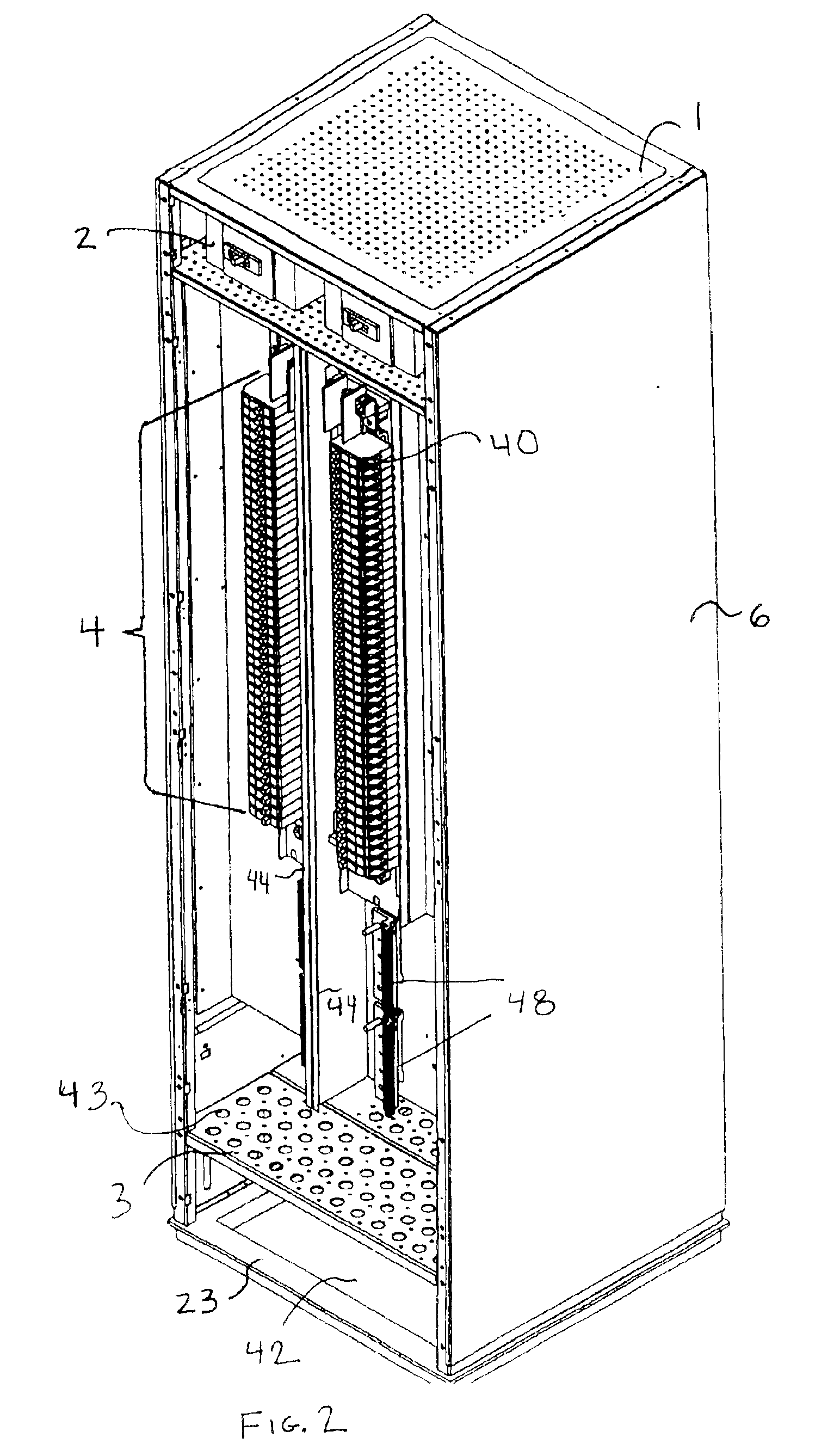
[0027]FIG. 2 illustrates a remote distribution cabinet in accordance with the present invention with the door removed and the outer side cover 6 attached. The remote distribution cabinet incl...


PUM


Abstract

The present invention is directed to an electrical equipment enclosure assembly, particularly those used to house power distribution equipment. The enclosure uses the internal structural members and panel components to form the enclosure frame. The present invention is also designed to be mounted in the 2 ft.×2 ft. (600 mm×600 mm) tile space provided in raised flooring. The enclosure is also provided with a junction box that is mounted beneath the raised flooring to allow users to terminate wiring.

Description

CROSS-REFERENCE TO RELATED APPLICATIONS[0001]This application claims the benefit of United States Provisional Patent Application Ser. No. 60 / 272,842, filed on Mar. 2, 2001 and having the title “Enclosure Assembly” and naming the same inventors identified herein, which provisional application is hereby incorporated by reference in its entirety.BACKGROUND OF THE INVENTION[0002]The influx of rack equipment in client / server, telecommunications process control, vibration monitoring, and numerous other electrical and electronic equipment environments has created a need for greater numbers of individual power branch circuits. These devices are smaller than the predecessors, more numerous, densely packed and consume less power. Because of this, most power distribution units expand their circuit breaker poles prior to exceeding their rated capacity. Present solutions to this problem require adding more electrical enclosures housing additional circuit breakers, or building larger, bulkier enc...

Claims


Application Information

Patent Timeline
Patent Type & Authority Patents(United States)
IPC IPC(8): H02B1/32H02B1/00H02B1/30
CPCH02B1/32H02B1/30
Inventor BAKER, ROBERT E.HARPER, MICHAEL R.MARTIN, JAMES K.MATHIS, RANDALL F.
Owner VERTIV CORP
Why Eureka
Try Eureka