Charged particle beam irradiation equipment and control method thereof

a technology of irradiation equipment and charged particles, which is applied in the field of charging particle beam irradiation equipment, can solve the problems of delayed output voltage generation, burden and inconvenience of patients, and difficulty in uniformizing the irradiation dose at the affected part, so as to reduce the irradiation time of the charged particle beam in the irradiation object, the effect of short time and short tim

Inactive Publication Date: 2005-04-19
HITACHI LTD
View PDF33 Cites 154 Cited by
  • Summary
  • Abstract
  • Description
  • Claims
  • Application Information

AI Technical Summary

Benefits of technology

[0011]According to the present invention, since the power supply has two power supply units of the first power supply unit having no filter and the second power supply unit having a filter, when the irradiation position of the charged particle beam in the irradiation object is changed over, the first power supply unit having no filter, namely a power supply unit having no delay element, is used to apply the voltage to the scanning electromagnet, so that the exciting current flowing in the scanning electromagnet can be changed in a short time. Therefore, the irradiation position of the charged particle beam can be changed over in a short time, and the irradiation time of the charged particle beam in the irradiation object can be reduced. On the other hand, wh

Problems solved by technology

If the dead time is longer, the treatment time will also be longer, causing a patient to be in burden and inconvenience.
On the contrary, if the beam irradiation is performed even when the irradiation position of the beam is being changed over, the irradiation dose applied in the period of time when the irradiation position of the beam is being changed over must be also considered to figure out the total dose at the affected part, and therefore it becomes difficult to make the irradiation dose at the affected part uniform.
However, since the power supply stated in the second conventional art employs a filter for removing the pulsating component, a

Method used


Image

  • Charged particle beam irradiation equipment and control method thereof
  • Charged particle beam irradiation equipment and control method thereof
  • Charged particle beam irradiation equipment and control method thereof

Examples


embodiment 1

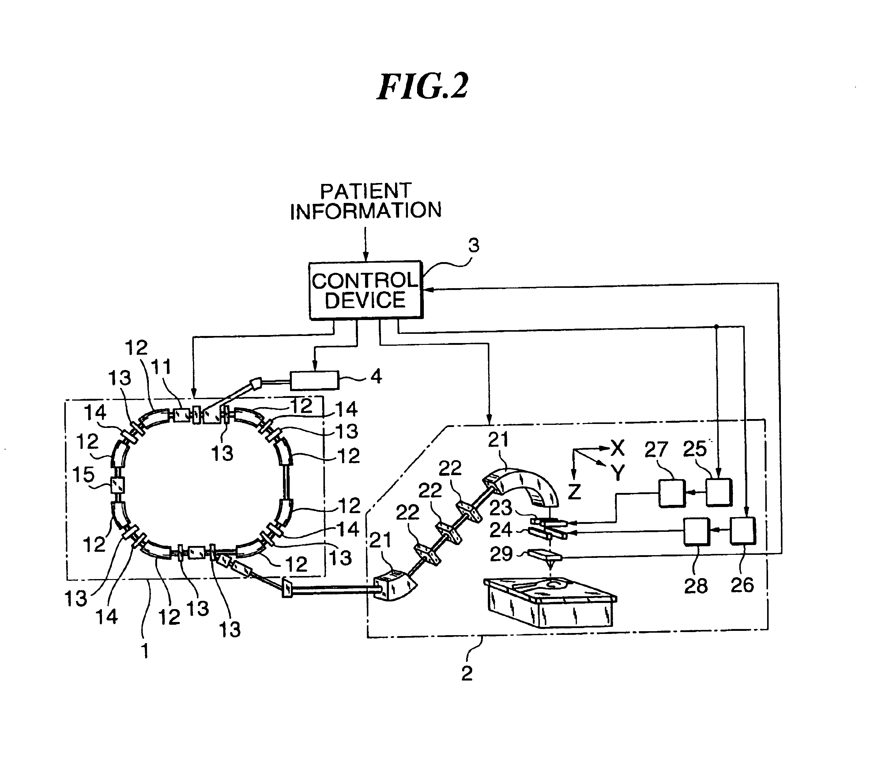
[0014]FIG. 2 shows the charged particle beam irradiation equipment of the preferred embodiment according to the present invention. By the way, the charged particle beam irradiation equipment of FIG. 2 is equipment for performing cancer treatment by applying a charged particle beam accelerated by a synchrotron 1 to the affected part of a cancer patient with a rotational irradiation device 2. Further, the charged particle beam irradiation equipment according to the present embodiment, as shown in FIG. 3, divides the affected part into a plurality of layered areas L1-L9 in a direction of beam propagation, and each layered area is further divided into a plurality of irradiation areas A11, A12, . . . , to each of which the beam is applied.

[0015]In the cancer treatment by means of the charged particle beam irradiation equipment of FIG. 2, first patient information such as the depth position of the affected part, the shape of the affected part, irradiation dose to be achieved in the affect...

embodiment 2

[0057]Referring to FIG. 7, the charged particle beam irradiation equipment, namely another embodiment of the present invention, will be described. The charged particle beam irradiation equipment according to this embodiment is different from the Embodiment 1 mainly in the configuration of the scanning electromagnet power supply. In the following described is different points from Embodiment 1.

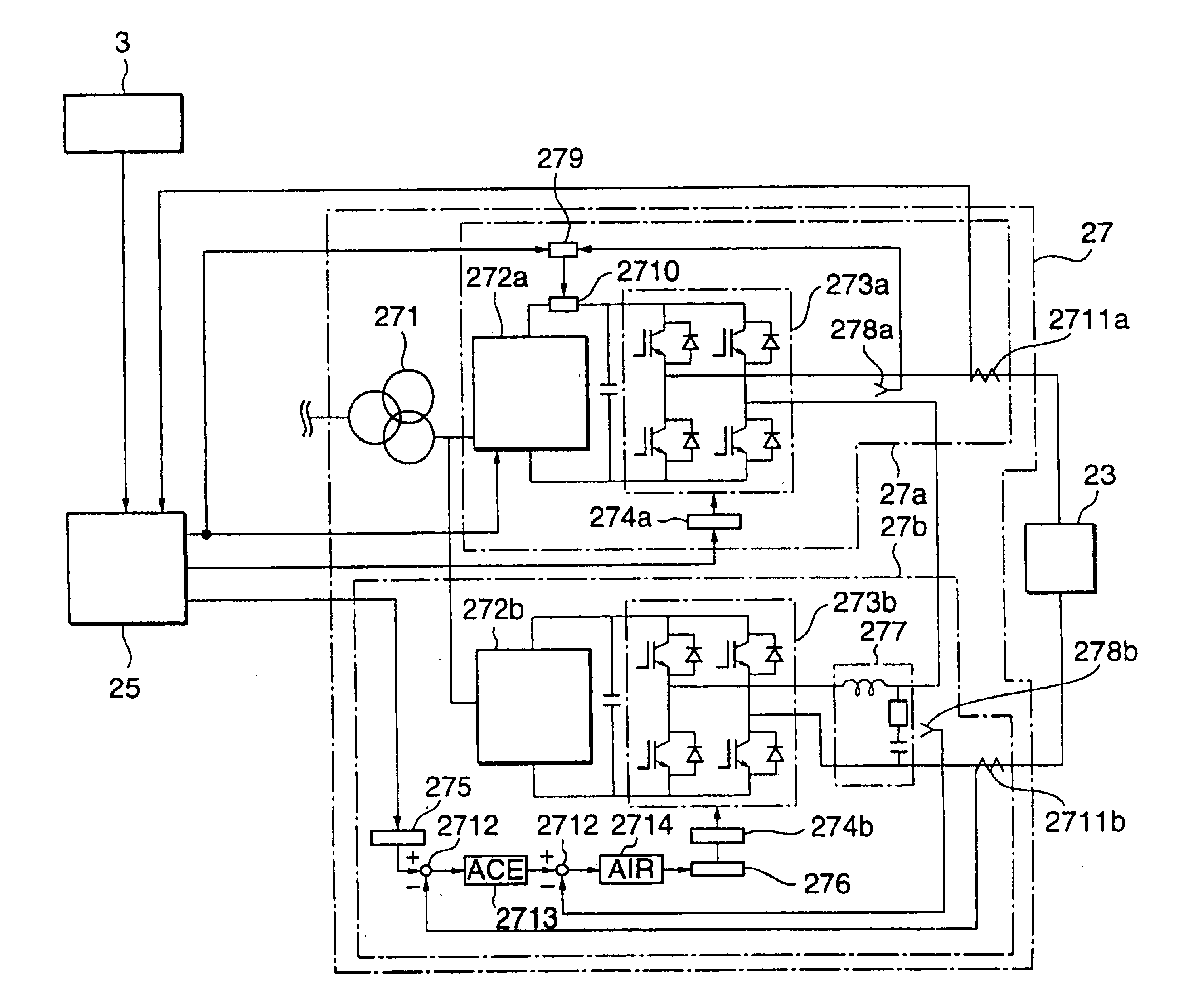
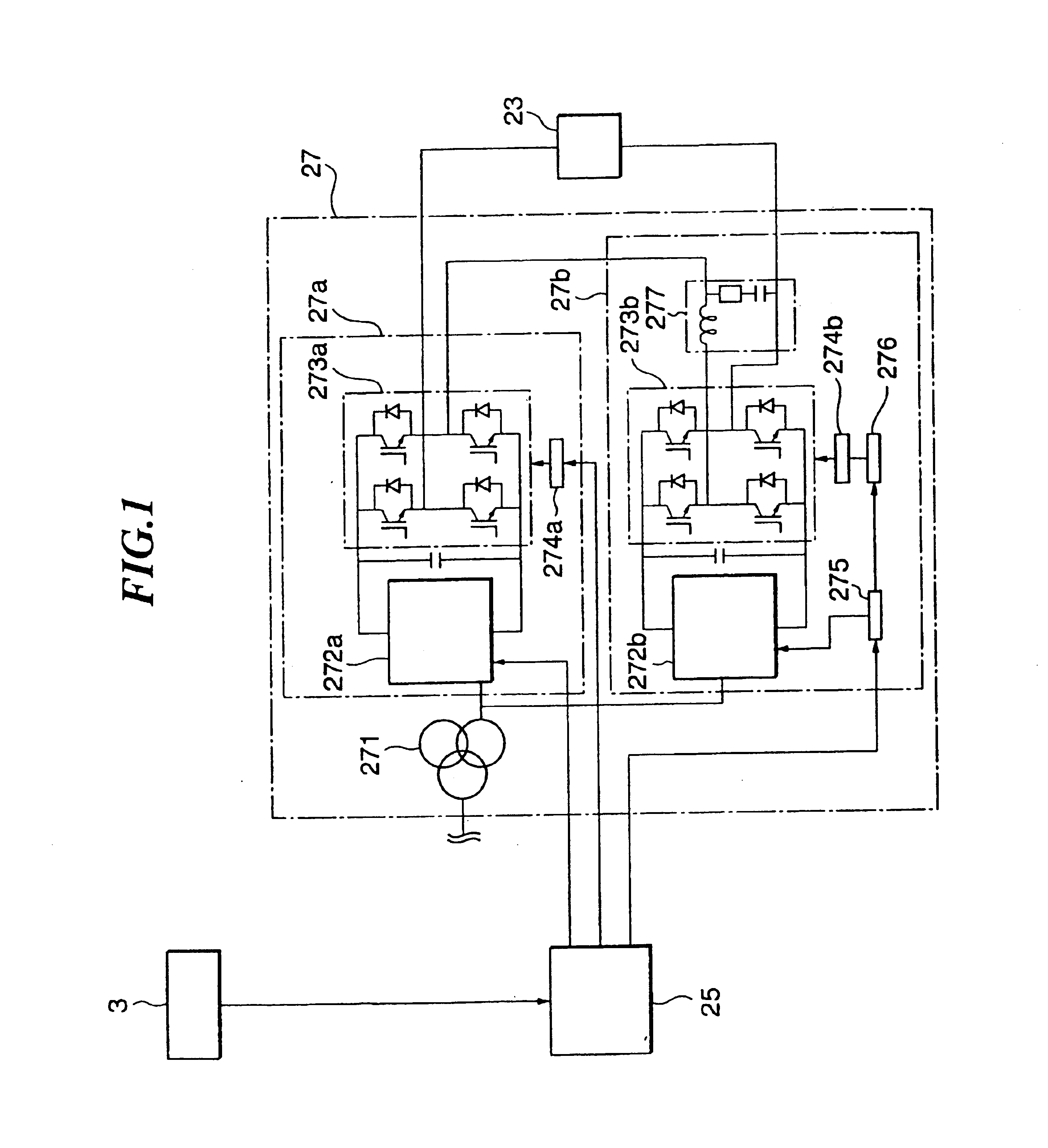
[0058]FIG. 7 shows a configuration of a scanning electromagnet power supply 27 according to the present embodiment. By the way, a scanning electromagnet power supply 28 has a similar configuration; therefore its explanation is omitted. Further, a total block diagram of the present embodiment is the same as Embodiment 1, as in FIG. 2.

[0059]In the FIG. 7, the power supply unit 27a has a voltage detector 278a, and the voltage detector 278a detects the output voltage of the inverter 273a, namely the output voltage of the power supply unit 27a. A voltage detected value detected by the voltage detect...


PUM


Abstract

A power supply for applying a voltage to a scanning electromagnet for deflecting a charged particle beam has a first power supply unit having no filter and a second power supply unit having a filter. When an irradiation position of the charged particle beam in an irradiation object is moved, the first power supply unit, namely a power supply unit having no filter, is used to apply the voltage to the scanning electromagnet, so that an exciting current flowing in the scanning electromagnet can be changed in a short time. Further, when the irradiation position of the charged particle beam is maintained, the second power supply is used to apply a voltage whose pulsating component was removed to the scanning electromagnet, so that the exciting current flowing in the scanning electromagnet can be controlled precisely. Consequently, the charged particle beam can be applied uniformly to the irradiation object and an irradiation time of the charged particle beam to the irradiation object can be curtailed.

Description

[0001]This application is a continuation application of U.S. Ser. No. 09 / 623,040, filed Aug. 25, 2000. This application is related to U.S. Ser. No. 10 / 287,656, filed Nov. 5, 2002.TECHNICAL FIELD[0002]The present invention relates to a charged particle beam irradiation equipment for irradiating an irradiation object with a charged particle beam, and its control method.BACKGROUND ART[0003]For a charged particle irradiation equipment for irradiating an irradiation object with a charged particle beam (hereinafter referred to as “beam”), a charged particle beam irradiation equipment for irradiating the affected part of a patient with a beam to perform cancer treatment is known, and in Japanese Published Unexamined Patent Application No. 9-223600 (hereinafter referred to as the “first conventional art”), as an example, described is a charged particle beam irradiation equipment for applying the beam to each irradiation area in order after the affected part was divided into a plurality of t...

Claims


Application Information

Patent Timeline
IPC IPC(8): A61N5/10G21K5/00G09G3/10G09G3/04H01J7/00H01J7/28G01Q10/00G01Q60/00G01Q60/50G21K1/08G21K1/093H05H7/04
CPCA61N5/10A61N5/1043H05H7/04G21K1/093A61N2005/1087
Inventor AKIYAMA, HIROSHIKUBO, HIROSHIHIRAMOTO, KAZUO
Owner HITACHI LTD
Why Eureka
Try Eureka