Jet nozzle spark plug

a technology of spark plugs and jet nozzles, which is applied in the direction of spark plugs, sparking plugs, basic electric elements, etc., can solve the problems of limited life of igniting electrodes as well as ground electrodes, limited ignition and conductive paths between electrodes, etc., and achieves a large volume of ignition in a relatively short period of time, high efficiency, and extremely fast burning of fuel/air mixtures

Inactive Publication Date: 2005-04-19
NGUYEN BILL
View PDF3 Cites 14 Cited by
  • Summary
  • Abstract
  • Description
  • Claims
  • Application Information

AI Technical Summary

Benefits of technology

[0012]Another object of the present invention is to provide a super jet spark plug having a ground electrode with a horn nozzle shape in spaced relationship to a spherically tipped ignitor electrode in order to burn a fuel / air mixture extremely fast so as to provide fuel efficiency and to burn clean.
[0013]Still a further object is to provide a spark plug discharging set of electrodes wherein the spark generated by the ignitor electrode passes to the ground electrode which is of a horn shape so as to burn mixed gasses and which is capable of generating a large volume ignition in a relatively short period of time in order to burn the mixed gasses very quickly whereby power is increased and the burn is clean and fuel efficiency is gained.

Problems solved by technology

Problems and difficulties have been encountered with conventional spark plugs which stem primarily from the fact that none have been able to obtain ultimate performance by providing better mixing of the fuel and air together so that better ignition and more uniform and efficient burning is obtained in the combustion chamber.
A part of the problem resides in that the surface area of the igniting electrode is limited and, therefore, the life of the igniting electrode as well as the ground electrode is limited and short lived.
Furthermore, the spark crossing the gap follows a linear path which again limits ignition and the conductive path between electrodes.

Method used


Image

  • Jet nozzle spark plug
  • Jet nozzle spark plug
  • Jet nozzle spark plug

Examples


Embodiment Construction

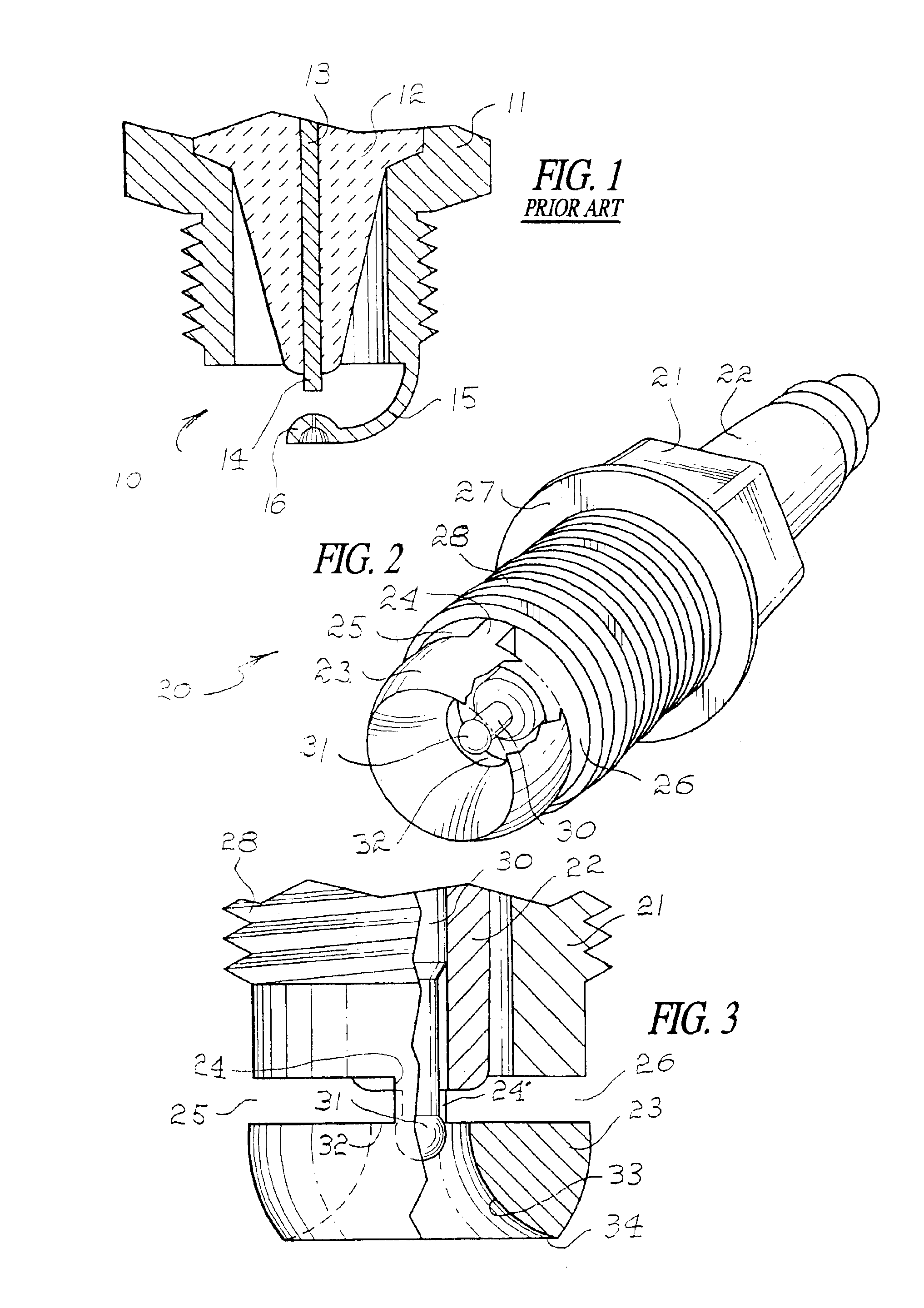
[0019]Referring to FIG. 1, a conventional tip of a spark plug is illustrated in the general direction of arrow 10 which includes a body 11 supporting an insulator 12 which, in turn, supports an ignitor electrode 13. It can be seen that the electrode 13 terminates at its distal end in a cylindrical tip 14 and that the tip is in fixed, spaced-apart relationship with respect to a ground electrode 15. The ground electrode 15 terminates at its distal end in a knob 16 which is fixed, spaced-apart relationship with respect to the tip 14 of the ignition electrode. Therefore, a substantial gap is defined between the two electrodes. However, it can be seen that the relative surface area of the electrodes is limited to the cylindrical shape of the tip 14 and the knob 16. Therefore, since only a limited surface area is available, extensive wear and debris build-up occurs rapidly. As the build-up continues, efficiency decreases.

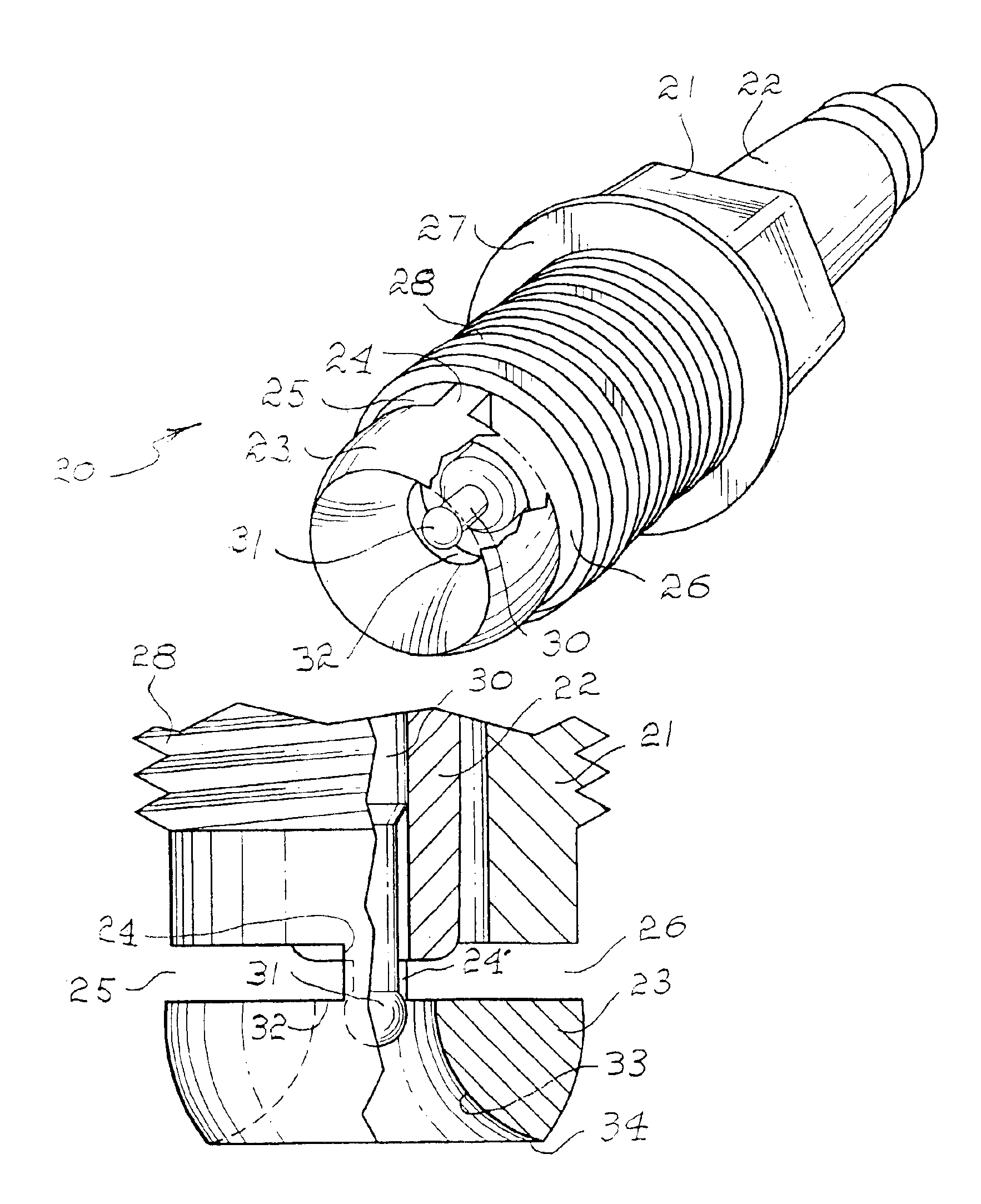
[0020]Referring now in detail to FIG. 2, it can be seen that the jet...


PUM


Abstract

A spark plug having a ground electrode in the shape of a horn nozzle defined by an enlarged mouth and a reduced throat joined together, a conical inner wall tapered from the mouth to the throat. An ignitor electrode terminates at its distal end in a spherical tip disposed in the throat in spaced-apart relationship with respect to the tapered inner wall. An insulative body supports the ignitor electrode with a conductive body supporting the ground electrode. The horn nozzle is joined with the conductive body by a pair of posts so as to define a pair of slots for venting exhaust gasses from the ignition site.

Description

[0001]Priority claimed on Ser. No. 60 / 471,755 filed May 20, 2003 abandoned.BACKGROUND OF THE INVENTION[0002]1. Field of the Invention[0003]The present invention relates to the field of spark plugs for internal combustion engines, and more particularly to a novel spark plug having a horn nozzle at its discharge end providing a narrow throat creating more concentrate of a fuel / air mixture than can be gained from conventional spark plugs.[0004]2. Brief Description of the Prior Art[0005]Spark ignition of an air / fuel mixture within a combustion chamber of an internal combustion engine involves the igniting of the mixture by an electric spark, closing a gap between an electrode, providing the spark and a ground electrode. Thus, in general, upon a downward stroke of a piston within a cylinder, the fuel / air mixture enters the combustion chamber from the carburetor or fuel injection system. Additional fuel / air mixture is then blocked-off upon completion of the compression stroke of the pisto...

Claims


Application Information

Patent Timeline
Patent Type & Authority Patents(United States)
IPC IPC(8): H01T13/20H01T13/32
CPCH01T13/32H01T13/28
Inventor NGUYEN, BILL
Owner NGUYEN BILL
Why Eureka
Try Eureka