Voltage detection circuit, power-on/off reset circuit, and semiconductor device

a voltage detection and reset circuit technology, applied in the direction of current/voltage detection, instruments, pulse techniques, etc., can solve the problems of difficult to properly terminate a sequence in operation, the memory data is destroyed in the memory circuit when the operation is immediately suspended, so as to prevent the wrong operation of non-volatile memory and stable voltage detection signal

Inactive Publication Date: 2005-04-19
RPX CORP
View PDF36 Cites 3 Cited by
  • Summary
  • Abstract
  • Description
  • Claims
  • Application Information

AI Technical Summary

Benefits of technology

[0023]The power-on / off reset circuit of the invention of claim 9 comprises a first voltage detection circuit which detects a first voltage and outputs a first signal, and prevents a new operational sequence when a power-supply voltage is equal to or lower than the first voltage.
[0034]The inventions of claims 1-8 and 14 are voltage detection circuits which reduce the peak of the current drain and obtain a stable voltage detection signal. There is another effect that the stable voltage detection signal can be obtained even at a low voltage of turning on the power-supply.

Problems solved by technology

On the other hand, when a predetermined voltage is detected by the voltage detection circuit, a power-on / off reset circuit for immediately suspending the operations of the devices such as a logic circuit or a memory circuit might destroy memory data in the memory circuit when the operation is immediately suspended.
For this reason, it is difficult to properly terminate a sequence in operation.

Method used


Image

  • Voltage detection circuit, power-on/off reset circuit, and semiconductor device
  • Voltage detection circuit, power-on/off reset circuit, and semiconductor device
  • Voltage detection circuit, power-on/off reset circuit, and semiconductor device

Examples


embodiment 1

(Embodiment 1)

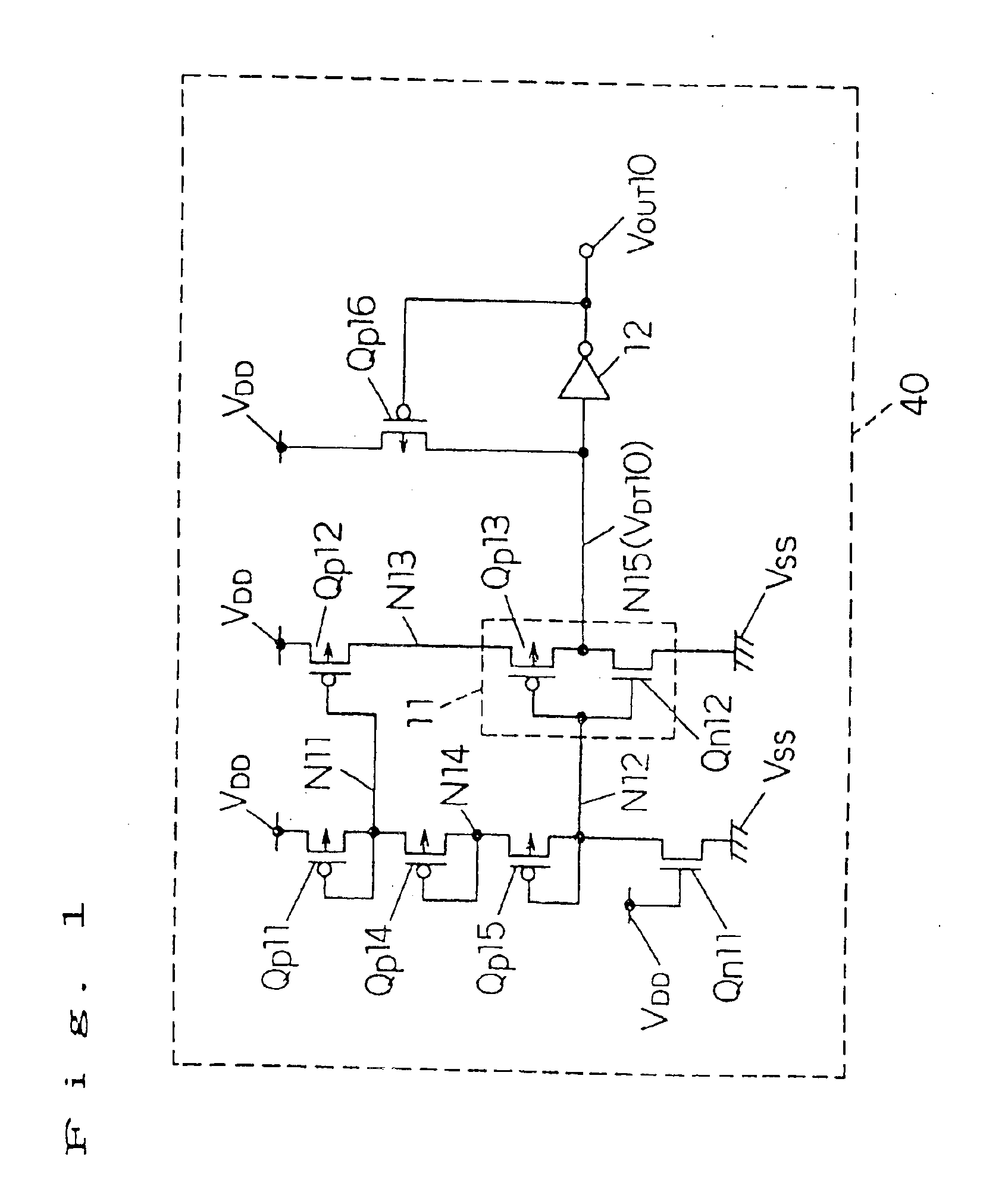
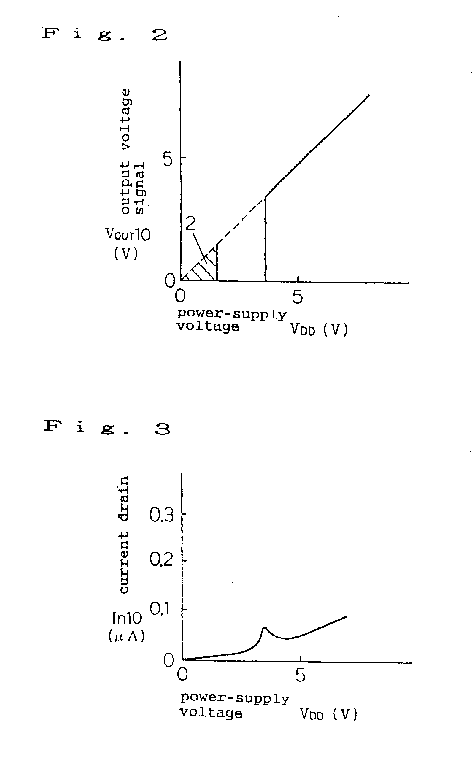
[0065]FIG. 1 shows the construction of the voltage detection circuit of the first embodiment of the present invention (corresponding to claims 1, 2, and 3). FIG. 2 shows the relationship between the power-supply voltage and the output voltage signal, and FIG. 3 shows the relationship between the power-supply voltage and the current drain.

[0066]The construction of the present embodiment will be explained hereinafter. In FIG. 1, Qp 11-Qp 16 are P-channel type MOS transistors, Qn 11 and Qn 12 are N-channel type MOS transistors, and 11 and 12 are NOT circuits.

[0067]The source of the P-channel type MOS transistor Qp 11 is connected with the power-supply voltage VDD, and its gate and drain are connected with the node N 11. The source of the P-channel type MOS transistor Qp 12 is connected with the power-supply voltage VDD, and its gate and drain are connected with the node N 11 and the node N 13, respectively. The P-channel type MOS transistors Qp 14 and Qp 15 are connected ...

embodiment 2

(Embodiment 2)

[0074]FIG. 4 shows the construction of the voltage detection circuit of the second embodiment of the present invention (corresponding to claim 4).

[0075]In the present embodiment, a voltage detection circuit 41 which can detect a lower voltage than in the first embodiment is added, the output signal VDT 20 whose logical voltage is “H” is supplied to the gate of the P-channel type MOS transistor Qp 17 at the low voltage of the voltage detection circuit 41, and this transistor Qp 17 is connected between the node N 15 and the power-supply voltage VDD. The present embodiment can prevent the circuit of FIG. 1 from becoming unstable at around 1.5V shown in FIG. 2.

[0076]As a result, this circuit can achieve a stable operation at a low voltage especially when the power supply is turned on, by means of a signal from a voltage detection circuit which detects a lower voltage than the voltage of the circuit itself.

embodiment 3

(Embodiment 3)

[0077]FIG. 5 shows the construction of the voltage detection circuit of the third embodiment of the present invention (corresponding to claims 5 and 6), and FIG. 6 shows the waveform of the output signal when the power supply is turned on.

[0078]The present embodiment can be used in the voltage detection circuit 41 of the second embodiment.

[0079]The sources of the P-channel type MOS transistors Qp 21-Qp 24, the gates of the transistors Qp 21 and Qp 24 are connected with the power-supply voltage VDD. The drains of the transistors Qp 21-Qp 22 and the gates of the transistors Qp 22-Qp 23 are connected with the node N 21. The drains of the transistors Qp 23-Qp 24 are connected with the node N 23. The source of the P-channel type MOS transistor Qp 25 is connected with the node N 21, and its gate and drain are connected with the node N 22. A resistance R 21 is connected between the node N 22 and the ground voltage VSS. The N-channel type MOS transistor Qn 21 whose gate is the...


PUM


Abstract

The present invention comprises a first MOS transistor whose gate and drain are connected with a first node, a second MOS transistor whose gate and drain are connected with the first node and a third node, respectively, a first resistive element which is connected between the first node and a second node, a second resistive element which is connected between the second node and a ground voltage terminal, a first NOT circuit whose input terminal is connected with the second node, whose output terminal is a fourth node, and which is connected between the third node and the ground voltage terminal, and a second NOT circuit whose input terminal is connected with the fourth node and whose output terminal is a fifth node. Consequently, the present invention can detect voltage in a stable condition with low power consumption.

Description

[0001]This application is a divisional of U.S. patent application Ser. No. 10 / 370,395, filed Feb. 20, 2003 (U.S. Pat. No. 6,822,493, issued Nov. 23, 2004), which is a continuation of U.S. patent application Ser. No. 09 / 803,775, filed Mar. 12, 2001 (U.S. Pat. No. 6,538,482, issued Mar. 25, 2003), which is a division of U.S. patent application Ser. No. 09 / 198,726, filed Nov. 24, 1998 (U.S. Pat. No. 6,246,624, issued Jun. 12, 2001), which is a division of U.S. patent application Ser. No. 08 / 817,746, filed Jul. 9, 1997 (U.S. Pat. No. 5,864,247, issued Jan. 26, 1999).FIELD OF THE INVENTION[0002]The present invention relates to a voltage detection circuit for detecting a power-supply voltage or the like, a power-on / off reset circuit, and a semiconductor device.BACKGROUND OF THE INVENTION[0003]Recently, a technique has become popular for operating a semiconductor device in a stable condition in a wide power-supply voltage range by changing the internal circuit operation in accordance with ...

Claims


Application Information

Patent Timeline
Patent Type & Authority Patents(United States)
IPC IPC(8): G01R19/00G01R19/165G01R19/155G01R19/145G06F1/28G11C11/22G11C5/14G11C8/00G11C8/08H03K17/22
CPCG01R19/0084G01R19/155G01R19/16538H03K17/223G11C5/143G11C8/08G11C11/22G06F1/28G01R19/00
Inventor HIRANO, HIROSHIGEASARI, KOUJISUMI, TATSUMI
Owner RPX CORP
Why Eureka
Try Eureka