Coil-embedded dust core and method for manufacturing the same, and coil and method for manufacturing the same

a technology of dust core and coil, which is applied in the direction of transformer/inductance coil/winding/connection inductance with magnetic core, etc., can solve the problems of joint failure, no consideration of connection parts between, and prone to failure during compression, etc., to reduce the number of processes required for manufacturing the coil, the effect of easy compression and high workability

Inactive Publication Date: 2005-04-19
TDK CORPARATION
View PDF18 Cites 41 Cited by
  • Summary
  • Abstract
  • Description
  • Claims
  • Application Information

AI Technical Summary

Benefits of technology

[0013]In view of the above, it is an object of the present invention to provide a coil-embedded dust core that is not prone to joint failures between a coil and terminal sections or to insulation failures of the coil and terminal section with respect to magnetic powder; that is more compact; and that can provide larger inductance; and to provide a method for manufacturing such a coil-embedded dust core.
[0014]The inventors have found that by using a coil that is formed by winding a flat conductor and both end sections thereof are formed on the same plane, a coil-embedded dust core can be made more compact while exhibiting larger inductance. That is to say, the present invention provides a coil-embedded dust core comprising a coil including a winding section in which a flat conductor having front and back surfaces opposed to each other with a predetermined distance, is wound; a first end section which is formed by the conductor and is extended from the winding section; and a second end section which is formed by the conductor and is extended from the winding section at a position different from the first end section, with the winding section being insulation coated, and a green body which is formed of insulation-coated ferromagnetic metal particles and in which the coil is embedded, wherein either one of the front and back surfaces of the first end section and either one of the front and back surfaces of the second end section are formed so as to be on the same plane.
[0015]In the coil-embedded dust core in accordance with the present invention, the conductor can be formed by a rectangular wire. Also, a part or the whole of each of the first and second end sections is preferably flattened by pressing. Further, the first and second end sections are preferably extended substantially in parallel with the conductor in the winding section. Also, in the coil-embedded dust core in accordance with the present invention, at least one of the first and second end sections has a bent section having a predetermined angle with respect to the winding section. In short, by this bent section, both of the end sections of the coil can be positioned on the same plane. Also, the ferromagnetic metal particles forming the green body are preferably composed of an Fe—Ni system alloy. Since the Fe—Ni system alloy has excellent workability, by making the ferromagnetic metal particles forming the green body an Fe—Ni system alloy, the green body can be made with a relatively low pressurizing force.
[0017]Also, the present invention provides a method for manufacturing a coil-embedded dust core, comprising a step (a) of charging raw material powder containing, as ingredients, soft magnetic metal powder and an insulating material forming the green body, into a cavity of a die; a step (b) of arranging the coil formed by winding a flat conductor which is insulation coated, in the cavity of the die into which the raw material powder has been charged; a step (c) of further charging the raw material powder into the cavity of the die so as to cover the coil; and a step (d) of compression forming the raw material powder. Here, it is effective that the soft magnetic metal powder forming the green body is Fe—Ni system alloy powder. Since the Fe—Ni system alloy powder has high workability and is easily compression formed, the coil-embedded dust core can be obtained without damaging the coil in the raw material powder. In the coil-embedded dust core in accordance with the present invention, the coil can include a winding section in which a flat conductor having front and back surfaces opposed to each other with a predetermined distance, is wound; a first end section which is formed by the conductor and is extended from the winding section; and a second end section which is formed by the conductor and is extended from the winding section at a position different from the first end section, and either one of the front and back surfaces of the first end section and either one of the front and back surfaces of the second end section can be formed so as to be on the same plane, and after the step (d), the method can further comprise a step (e) of bending the first and second end sections of the coil along the green body. This bending step (e) is especially effective in the case where the coil-embedded dust core is used as a surface mounting terminal section. Also, in the step (b), the whole or a part of each of the first and second end sections of the coil is preferably located on the outside of the cavity of the die. This is because the first and second end sections of the coil function as the terminal section, so that joint failure is less liable to occur at the time of wire connection in the case where the end sections are located on the outside of the green body.
[0018]Further, the present invention provides a coil comprising a winding section in which a flat conductor having front and back surfaces opposed to each other with a predetermined distance, is wound; a first end section which is formed by the conductor and is extended from the winding section; and a second end section which is formed by the conductor and is extended from the winding section at a position different from the first end section, wherein either one of the front and back surfaces of the first end section and either one of the front and back surfaces of the second end section are formed so as to be on the same plane. In this coil, the first and second end sections are preferably extended to symmetrical positions with respect to the winding section. This eliminates a need for distinguishing the direction of coil when the coil is handled.
[0019]Also, the present invention provides a method for manufacturing a coil, comprising a step of obtaining a winding coil having a pair of terminal sections; and a step of subjecting the paired terminal sections of the obtained winding coil to sizing process in a state in which a predetermined pressing force is applied or immediately after a predetermined pressing force is applied. In the sizing process, the paired terminal sections can be formed into a rectangular shape which is wider than other sections of the coil. In the method for manufacturing a coil in accordance with the present invention, press processing and sizing process are performed substantially at the same time, so that the number of processes required for manufacturing the coil can be decreased. Also, a step of bending either one or both of the paired terminal sections may be performed so that distances from a predetermined reference plane to the paired terminal sections are made substantially equal before or after sizing process or substantially simultaneously with the sizing process.

Problems solved by technology

In this case, connection parts are inside the magnetic body, which makes them prone to failures while compressing.
However, no consideration has been given to connection parts between the coil and terminal sections, and joint failures (including poor joining) are likely to occur due to the fact that joining is difficult since it takes place between the magnetic body section and an electrode at the interface with the core.
Here again, part of the terminal that forms a connection part with the coil is inside the core, which makes it prone to failures in the connection parts during the process to form a unitary structure.
Failures are likely to occur in the connection parts in this case as well.
Namely, the coil-embedded dust core or the inductor in Japanese Patent-Laid-Open Nos. 5-291046 and 11-273980, and Japanese Patent No. 2958807 has a coil and terminal sections embedded within magnetic powder, which makes it prone to joint failures between the coil and the terminal sections or insulation failures of the coil and the terminal sections with respect to the magnetic powder.
When a joint failure or an insulation failure occurs, it is difficult to determine the cause of the failure and in many cases takes a long time, since the coil and the terminal sections form connection parts inside the magnetic powder.
Furthermore, the inductor described in Japanese Patent No. 3108931 entails a high possibility for a joint failure to occur in connection parts between a coil and terminal sections after molding, due to the fact that a dust core is made using a coil that already has connection parts formed with terminal sections.
When a joint failure occurs in a connection part, determining the cause is difficult and time-consuming.

Method used


Image

  • Coil-embedded dust core and method for manufacturing the same, and coil and method for manufacturing the same
  • Coil-embedded dust core and method for manufacturing the same, and coil and method for manufacturing the same
  • Coil-embedded dust core and method for manufacturing the same, and coil and method for manufacturing the same

Examples


example

[0101]The coil-embedded dust core in accordance with the present invention will be described in detail by using an example.

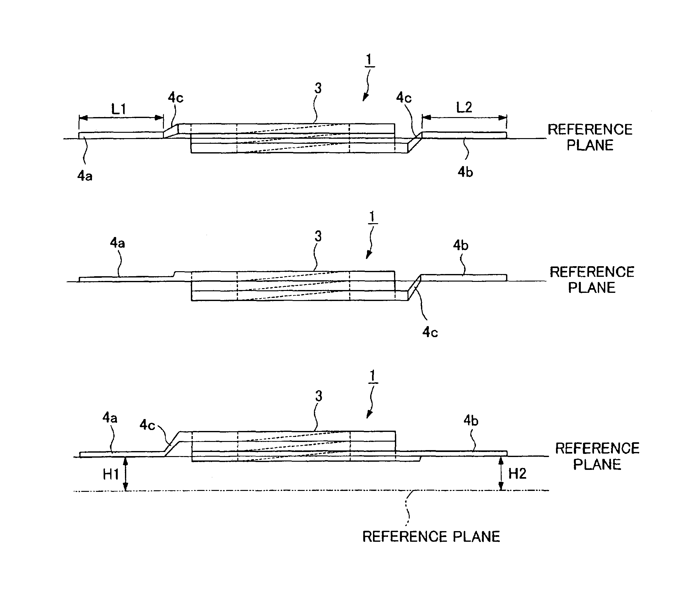
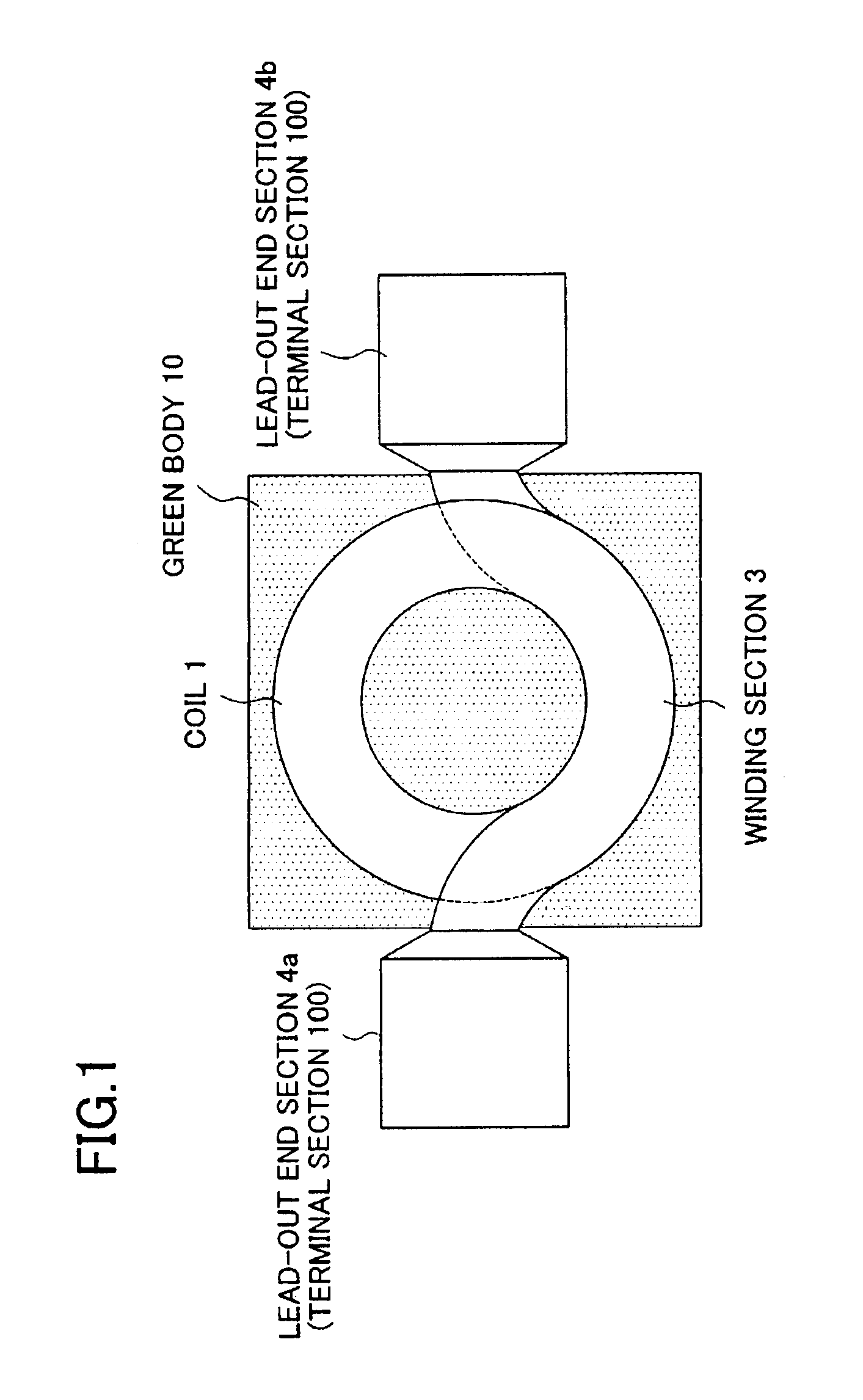
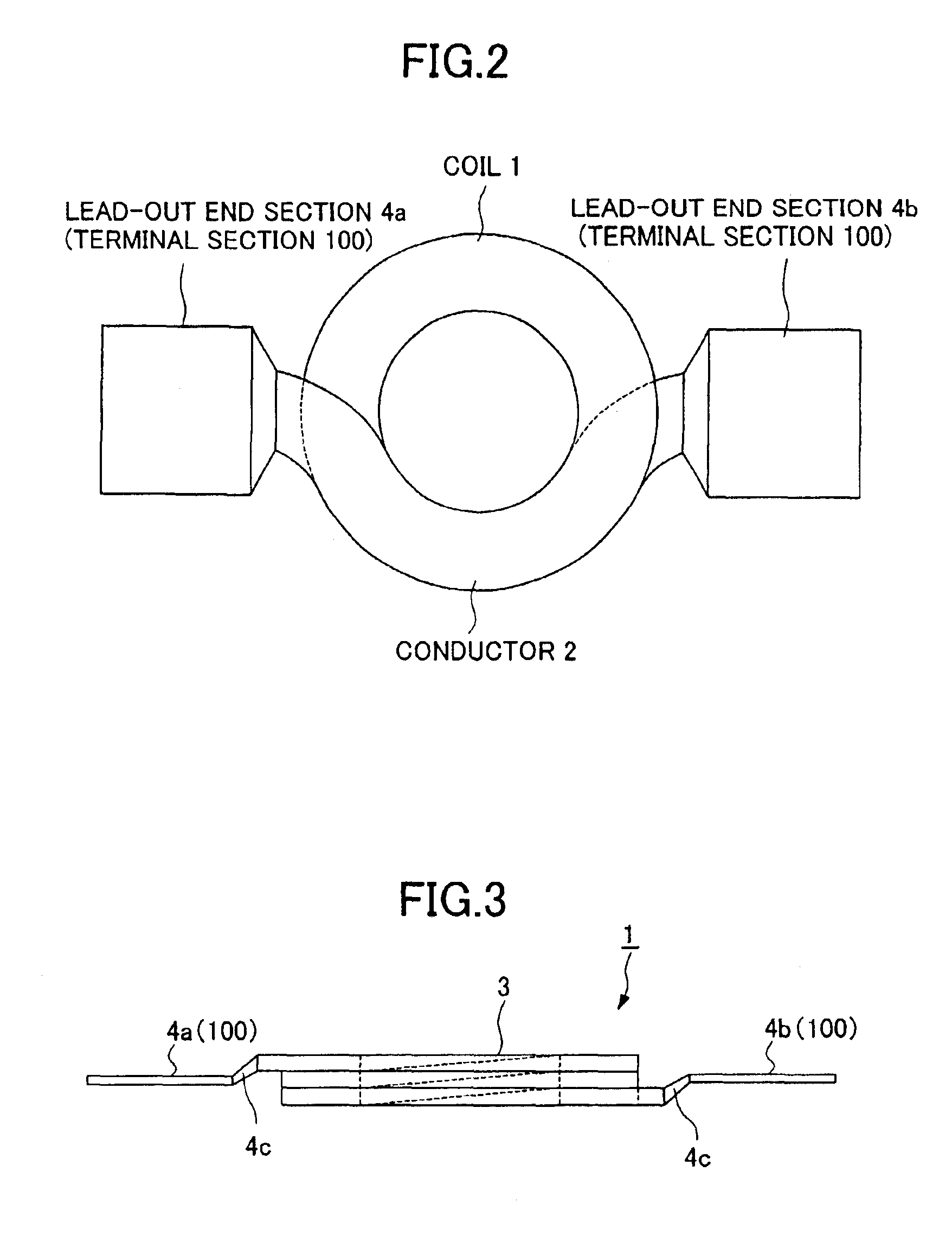
[0102]An experiment conducted to ascertain the inductance value of the coil-embedded dust core in the case where the coil 1 in which the lead-out end sections 4a and 4b are formed on the same plane by bending and the coil 200 in which the lead-out end sections 4a and 4b are not formed on the same plane are used is explained as the example. Both of the coil 1 and the coil 200 are formed by winding the conductor 2 2.5 turns.

[0103]Twenty samples of the coil-embedded dust core were made according to the following procedure:

[0104]The following were prepared:

[0105]Magnetic powder: Permalloy powder manufactured through atomizing method (45% Ni—Fe; mean particle size 25 μm)

[0106]Insulating material: silicone resin (SR2414LV by Toray Dow Corning Silicone Co., Ltd.)

[0107]Cross-linking agent: organic titanate (TBT B-4 by NIPPON SODA CO., LTD.)

[0108]Lubricant: aluminum stea...


PUM

PropertyMeasurementUnit
aspect ratioaaaaaaaaaa
wt %aaaaaaaaaa
thicknessaaaaaaaaaa

Abstract

There are provided a coil-embedded dust core that provides high inductance and a method for manufacturing the same. The coil-embedded dust core includes a coil 1 formed by winding a flat conductor 2 and a green body 10 comprising of ferromagnetic metal powder coated with an insulating material. The coil 1 is composed of a winding section 3 in which the flat conductor 2 having front and back surfaces opposed to each other with a predetermined distance is wound and lead-out end sections 4a and 4b that are extended from the winding section 3. Either one of the front and back surfaces of the lead-out end section 4a and either one of the front and back surfaces of the lead-out end section 4b are formed so as to be on the same plane. By using the coil 1 in which the both end sections (lead-out end sections 4a and 4b) are formed on the same plane, the coil-embedded dust core can be made smaller in size, and high inductance can be provided.

Description

BACKGROUND OF THE INVENTION[0001]1. Field of the Invention[0002]The present invention relates to a coil-embedded dust core, which may be used in inductors having a unitary structure with a magnetic core and in other electronic components. The present invention also relates to a method for manufacturing the coil-embedded dust core.[0003]2. Description of the Related Art[0004]In recent years, electric and electronic equipment has become more compact, and dust cores that are compact (low in height) yet able to accommodate large current have come to be in demand.[0005]Materials used for dust cores are ferrite powder and ferromagnetic metal powder, but ferromagnetic metal powder has larger saturation magnetic flux density than ferrite powder and its DC bias characteristics may be maintained even in a strong magnetic field. Consequently, in making a dust core that can accommodate large current, using ferromagnetic metal powder as a material for dust core has become mainstream.[0006]In add...

Claims


Application Information

Patent Timeline
Patent Type & Authority Patents(United States)
IPC IPC(8): H01F27/255H01F41/02H01F27/02H01F27/29H01F27/28H01F41/04H01F17/04H01F1/22
CPCH01F27/027H01F27/255H01F41/0246H01F27/022H01F2017/046H01F27/29H01F41/04H01F27/2847
Inventor MORO, HIDEHARUSUZUKI, TSUNEO
Owner TDK CORPARATION
Why Eureka
Try Eureka