Particles for electrophoretic display and electrophoretic display apparatus using them

a technology of electrophoretic display and electrophoretic display apparatus, which is applied in the direction of electrographic process apparatus, instruments, optics, etc., can solve the problems of ineffective cancellation of disadvantages, visual tension, and inability to easily identify letters and characters in the imag

Inactive Publication Date: 2005-04-19
CANON KK
View PDF14 Cites 9 Cited by
  • Summary
  • Abstract
  • Description
  • Claims
  • Application Information

AI Technical Summary

Benefits of technology

[0017]A first embodiment of the present invention is electrophoretic displaying particles comprised of a resin and pigment granules enclosed therein, having an average

Problems solved by technology

However, the liquid displaying devices have disadvantages that letters and characters in the image are not readily identifiable depending on the viewing angle

Method used


Image

  • Particles for electrophoretic display and electrophoretic display apparatus using them
  • Particles for electrophoretic display and electrophoretic display apparatus using them
  • Particles for electrophoretic display and electrophoretic display apparatus using them

Examples


example 1

[0112]An example of the displaying particles containing a granular black pigment is shown below.

[0113]A 35 g portion of resin dispersion liquid A, 1 g of divinyl benzene, and 0.35 g of a polymerization initiator AIBN (azoisobutyronitrile) were mixed sufficiently and the mixture was deaerated by an ultrasonic dispersing machine for 10 minutes. This mixture was put into mixture liquid C, and emulsified by an emulsifying machine. This emulsified liquid was sealed in a bottle with a silicone plug, and deaerated sufficiently by pressure reduction. Gaseous nitrogen was introduced therein. The emulsified mixture was allowed to react at 70° C. for 10 hours to form particles. After cooling, the reaction mixture was taken out. The calcium carbonate therein was decomposed by a sufficient amount of diluted hydrochloric acid. The particles were collected by filtration and washed with water to obtain electrophoretic displaying particles 1 containing a black pigment. The obtained particles had an ...

example 2

[0115]An example of the displaying particles containing a granular white pigment is shown below.

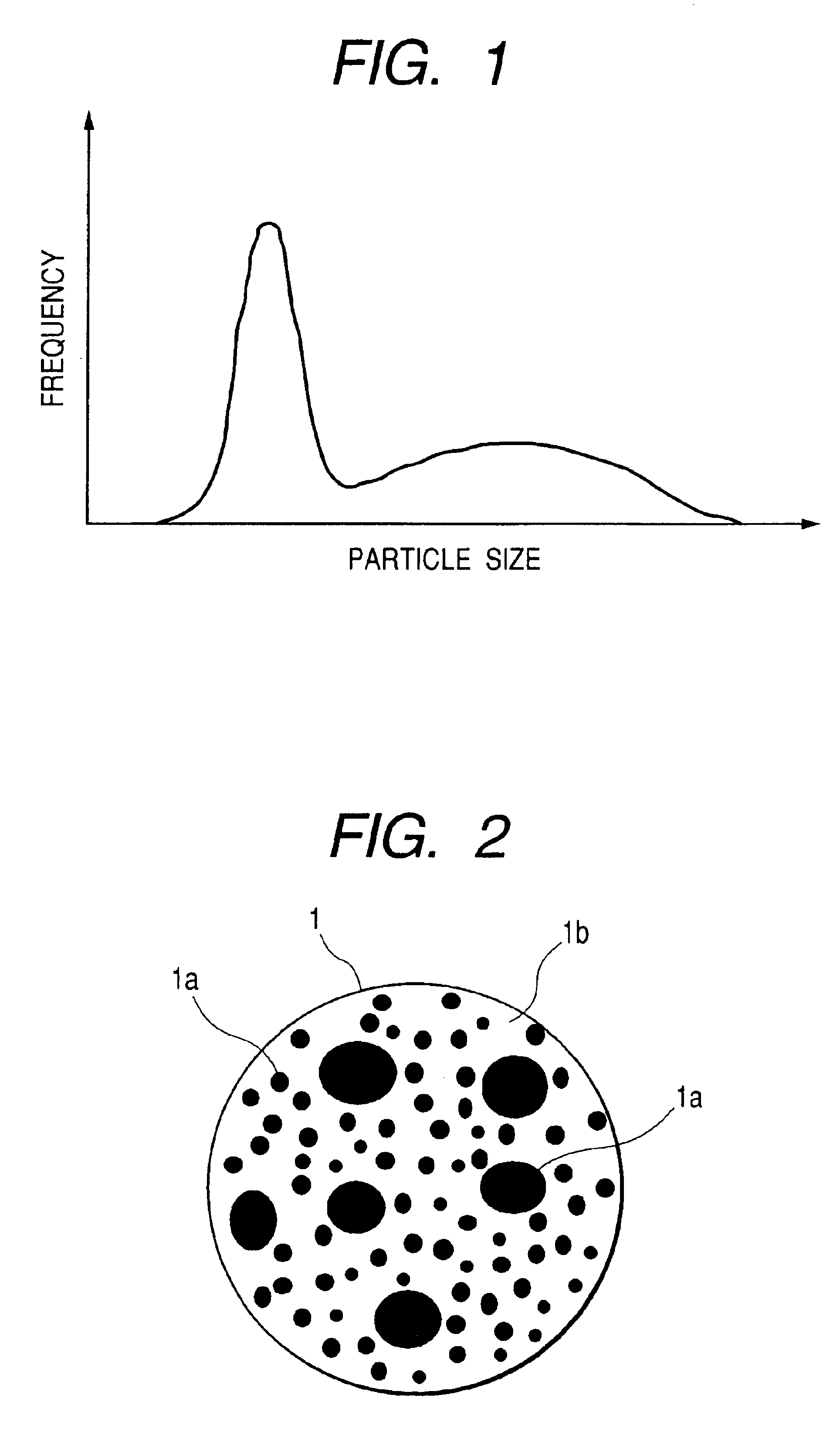
[0116]Electrophoretic displaying particles 1 containing a white pigment was prepared in the same manner as in Example 1 except that resin dispersion liquid A in Example 1 was replaced by 15 g of resin dispersion liquid A1 and 20 g of resin dispersion liquid A2. This electrophoretic displaying particles 1 was found to have an average particle size of 3 μm by particle size measurement. The electrophoretic displaying particles 1 were found to be polymer particles enclosing granular pigment 1a therein as shown in FIG. 2 by electron microscopy observation. Granular pigment 1a had a maximum granule diameter of about 800 nm.

example 3

[0117]Examples of three kinds of displaying particles containing a granular color pigment of red, green, or blue are shown below.

[0118]Three kinds of displaying particles 1 were prepared in the same manner as in Example 1 except that resin dispersion liquid A was replaced by resin dispersion liquid AR, resin dispersion liquid AG, or resin dispersion liquid ABu. The electrophoretic red displaying particles 1 contained a red pigment consisting of a mixture of red pigments of average granule diameters of 10 nm and 500 nm. The electrophoretic green displaying particles 1 contained a green pigment consisting of a mixture of green pigments of average granule diameters of 30 nm and 100 nm. The electrophoretic blue displaying particles 1 contained a blue pigment consisting of a mixture of blue pigments of average granule diameters of 20 nm and 200 nm.


PUM


Abstract

Electrophoretic displaying particles are provided. The particle is comprised of a resin and pigment granules enclosed therein. The pigment granules have an average particle size ranging from 0.1 μm to 20 μm, and the granule diameter distribution has two or more frequency maximums. This electrophoretic displaying particulate has high masking performance, improving the displaying contrast of the displaying device.

Description

BACKGROUND OF THE INVENTION[0001]1. Field of the Invention[0002]The present invention relates to particles for electrophoretic display, a liquid dispersion of the particles for electrophoretic display, and an electrophoretic displaying device utilizing migration of the electrophoretic particles.[0003]2. Related Background Art[0004]In recent years, with development of information instruments, needs are increasing for thin low-power-consuming displaying device as well as printing mediums, and research and development are being conducted actively for the displaying device to meet the needs.[0005]Particularly, liquid crystal displaying devices, which utilizes change of optical properties of the liquid crystal by controlling electrically the arrangement of the liquid crystal molecules, are being actively developed and are commercialized. Colorization is also being developed for more natural display. In the colorization, color images are displayed by using color filters and liquid crystal...

Claims


Application Information

Patent Timeline
IPC IPC(8): G02F1/01G02F1/167
CPCG02F1/167
Inventor MOTOI, TAIKOUENO, RIEIIMURA, AKIKOTAKAGI, SHINYA
Owner CANON KK
Why Eureka
Try Eureka