Thin-film magnetic head and method of manufacturing same, and slider of thin-film magnetic head and method of manufacturing same

Inactive Publication Date: 2005-04-19
HEADWAY TECH INC +1
View PDF18 Cites 2 Cited by
  • Summary
  • Abstract
  • Description
  • Claims
  • Application Information

AI Technical Summary

Benefits of technology

[0037]A second object of the invention is, in addition to the aforementioned first object, to provide a slider for a thin-film magnetic head and a method of manufacturing same, which make it possible to reduce the

Problems solved by technology

Thus, the conventional method involves a large number of steps for manufacturing a slider, which increases the manufacturing cost of the slider.
On the other hand, as the magnetic space is reduced, the slider is likely to collide with the recording medium, which can result in damage to the recording medium and the thin-film magnetic head element.
This results in a problem that the slider is harder to take off from the recording medium when the recording medium starts rotation from a resting state in which the slider is in contact with the recording medium.
This results in a problem that the MR height can deviate from its desired value.
Further, according to this method, when the air bearing surface of the bar is lapped on the concave surface plate, the bar can be scrat

Method used


Image

  • Thin-film magnetic head and method of manufacturing same, and slider of thin-film magnetic head and method of manufacturing same
  • Thin-film magnetic head and method of manufacturing same, and slider of thin-film magnetic head and method of manufacturing same
  • Thin-film magnetic head and method of manufacturing same, and slider of thin-film magnetic head and method of manufacturing same

Examples


second modified embodiment

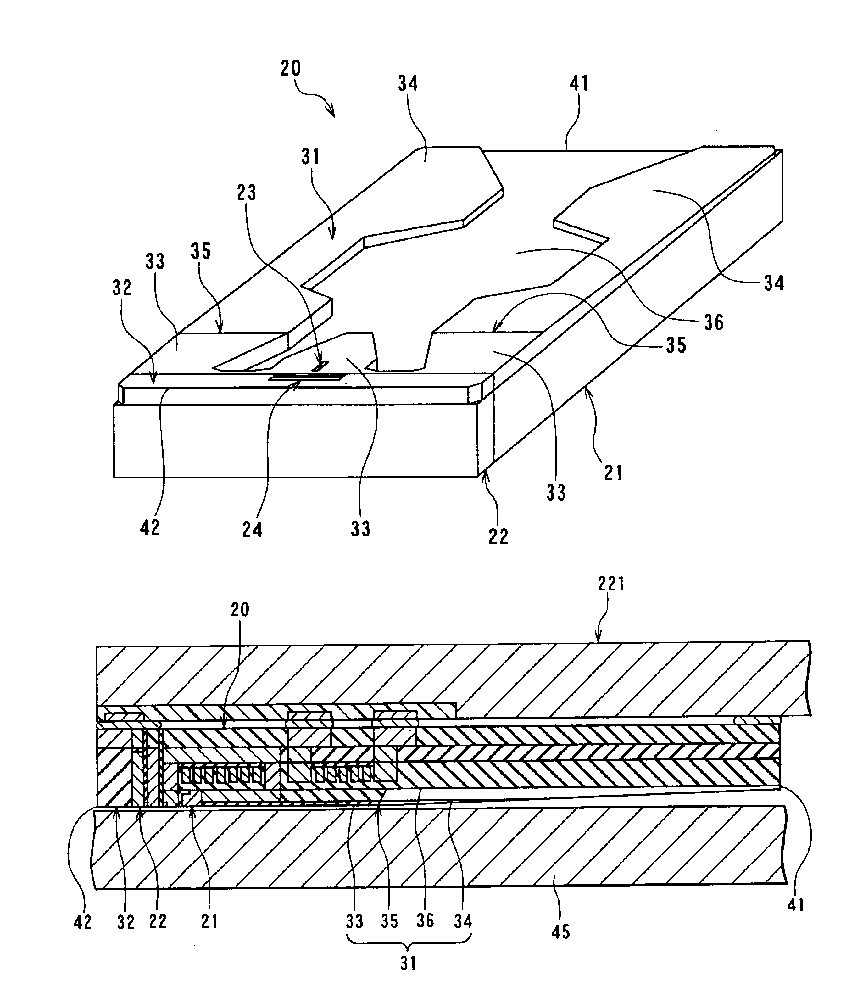
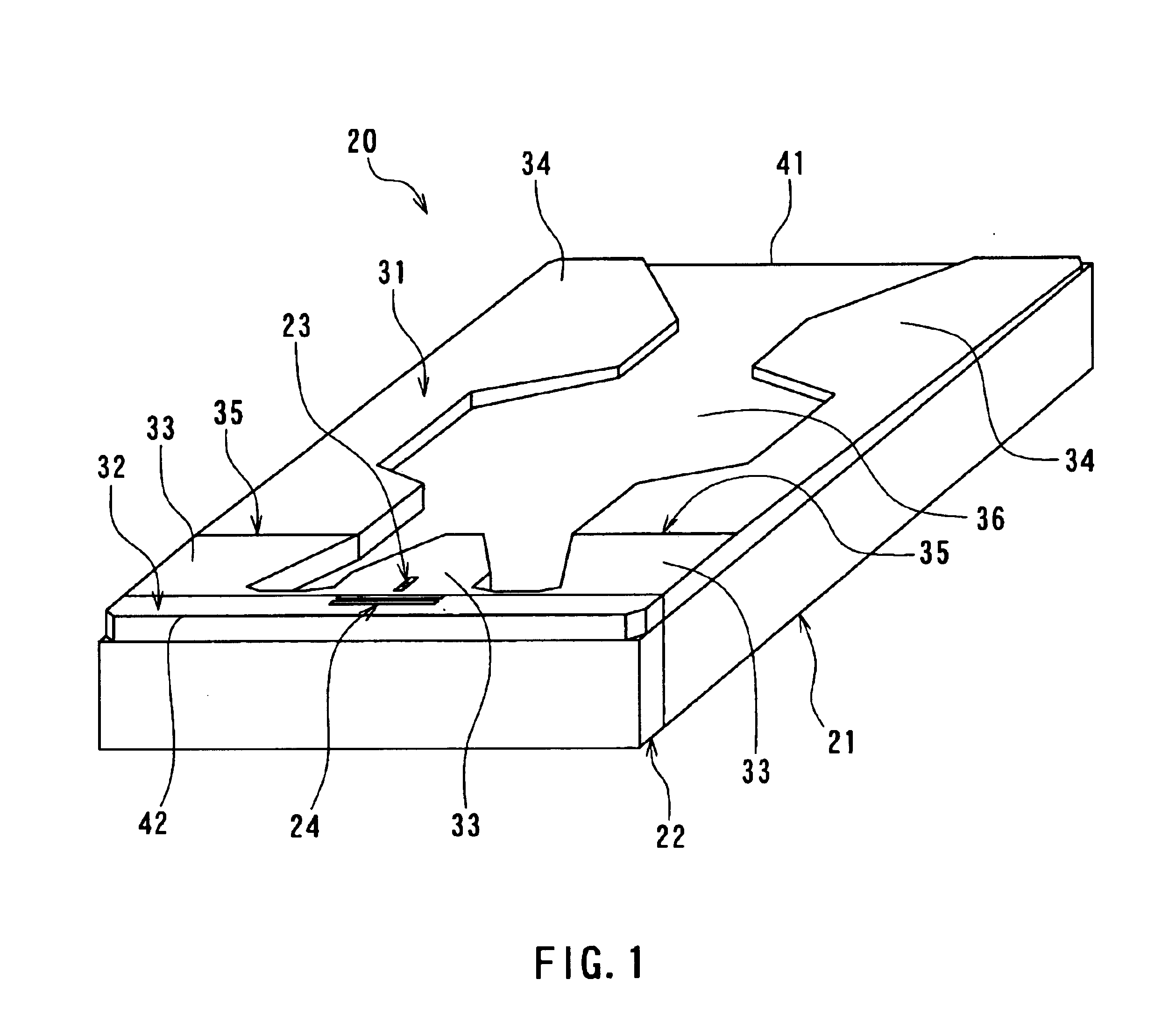
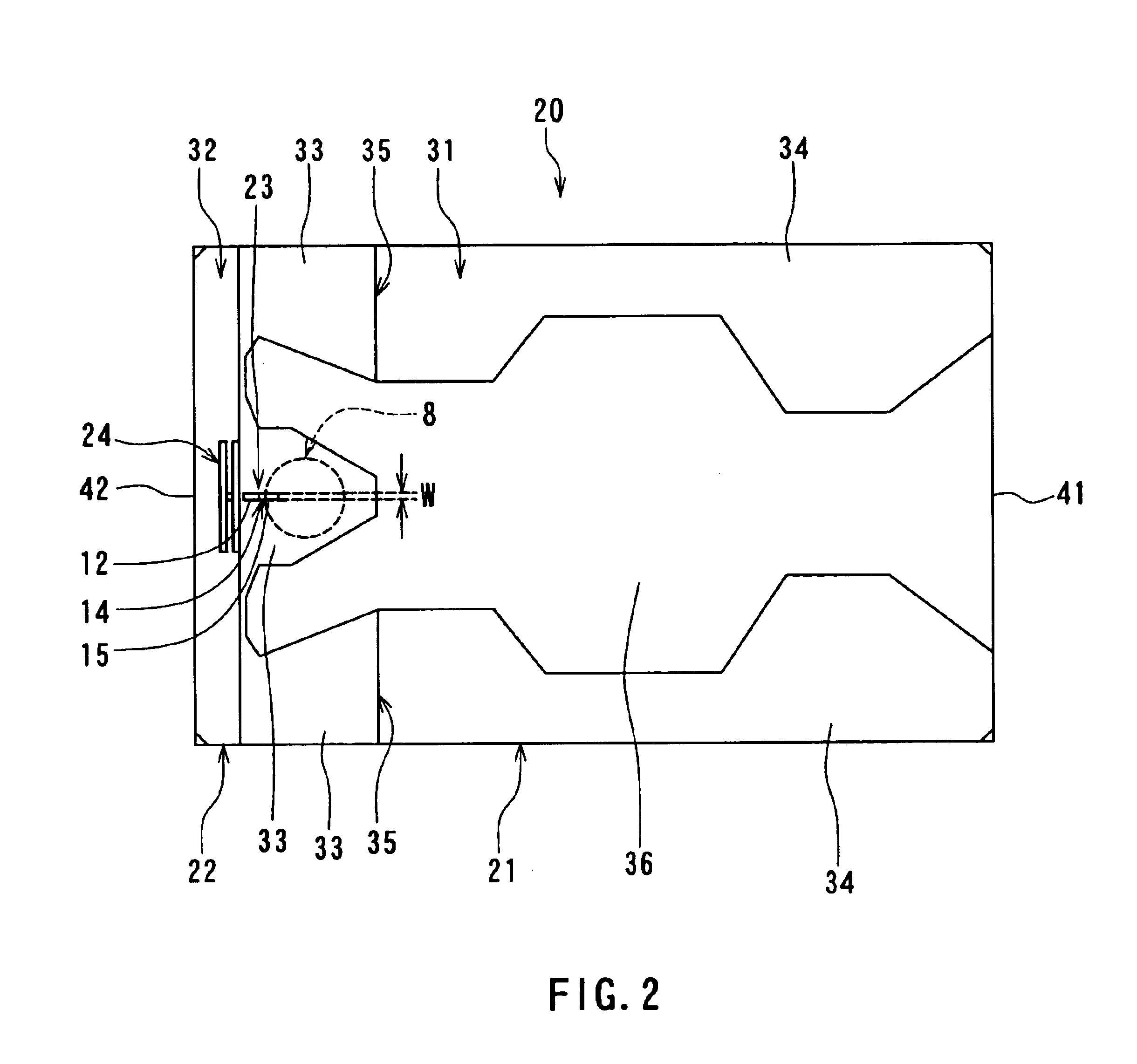
[0223]The slider 20 of the third modified example may be one which is off the surface of the recording medium 45 during the rotation of the recording medium 45 and comes into contact with the surface of the recording medium 45 when the recording medium 45 is at rest, like the slider 20 shown in FIGS. 1 and 2. Otherwise, it may be one in which the slider section 21 is in contact with the surface of the recording medium 45 at the border portion 35 regardless of whether the recording medium 45 is rotating or at rest, like the

[0224]According to the slider 20 of the third modified example, the area of the slider section 21 contacting the surface of the recording medium 45 is smaller than in the case where no recesses 38 are provided. Frictional resistance between the slider section 21 and the surface of the recording medium 45 is thereby reduced.

[0225]The invention is not limited to the foregoing embodiment, and various modifications may be made thereto. For example, the slider of the in...


PUM

PropertyMeasurementUnit
Thicknessaaaaaaaaaa
Distanceaaaaaaaaaa
Magnetoresistanceaaaaaaaaaa

Abstract

A slider comprises a slider section and a reproducing head section. The slider section has a first medium facing surface, an air inflow end, and a recording head. The reproducing head section has a second medium facing surface, an air outflow end, and a reproducing head. The slider section and the reproducing head section are fabricated separately, and bonded to each other so that the first medium facing surface and the second medium facing surface are continuous.

Description

BACKGROUND OF THE INVENTION[0001]1. Field of the Invention[0002]The present invention relates to a thin-film magnetic head having both a recording head and a reproducing head and a method of manufacturing the same, and a slider for a thin-film magnetic head having both a recording head and a reproducing head and a method of manufacturing the same.[0003]2. Description of the Related Art[0004]Performance improvements in thin-film magnetic heads have been sought as areal recording density of hard disk drives has increased. Such thin-film magnetic heads include composite thin-film magnetic heads that have been widely used. A composite head is made of a layered structure including a recording head having an induction-type electromagnetic transducer for writing and a reproducing head having a magnetoresistive element (that may be hereinafter called an MR element) for reading. MR elements include an anisotropic magnetoresistive (AMR) element that utilizes the AMR effect and a giant magneto...

Claims


Application Information

Patent Timeline
IPC IPC(8): G11B5/33G11B5/39G11B5/60G11B5/31
CPCG11B5/3103G11B5/313G11B5/332G11B5/3967G11B5/6005G11B5/3116G11B5/3163Y10T29/49044Y10T29/49798Y10T29/49055Y10T29/49155Y10T29/49041Y10T29/49032
Inventor SASAKI, YOSHITAKAKAMIGAMA, TAKEHIRO
Owner HEADWAY TECH INC
Why Eureka
Try Eureka