

Slider of thin-film magnetic head and method of manufacturing same
a thin-film magnetic head and slider technology, applied in the direction of maintaining the head carrier alignment, recording information storage, instruments, etc., can solve the problems of large number of steps for manufacturing the slider, damage to the recording medium and the thin-film magnetic head element, and high manufacturing cost of the slider. , to achieve the effect of reducing the magnetic space and being easy to manufactur
- Summary
- Abstract
- Description
- Claims
- Application Information
AI Technical Summary
Benefits of technology
Problems solved by technology
Method used
Image

Examples
first embodiment
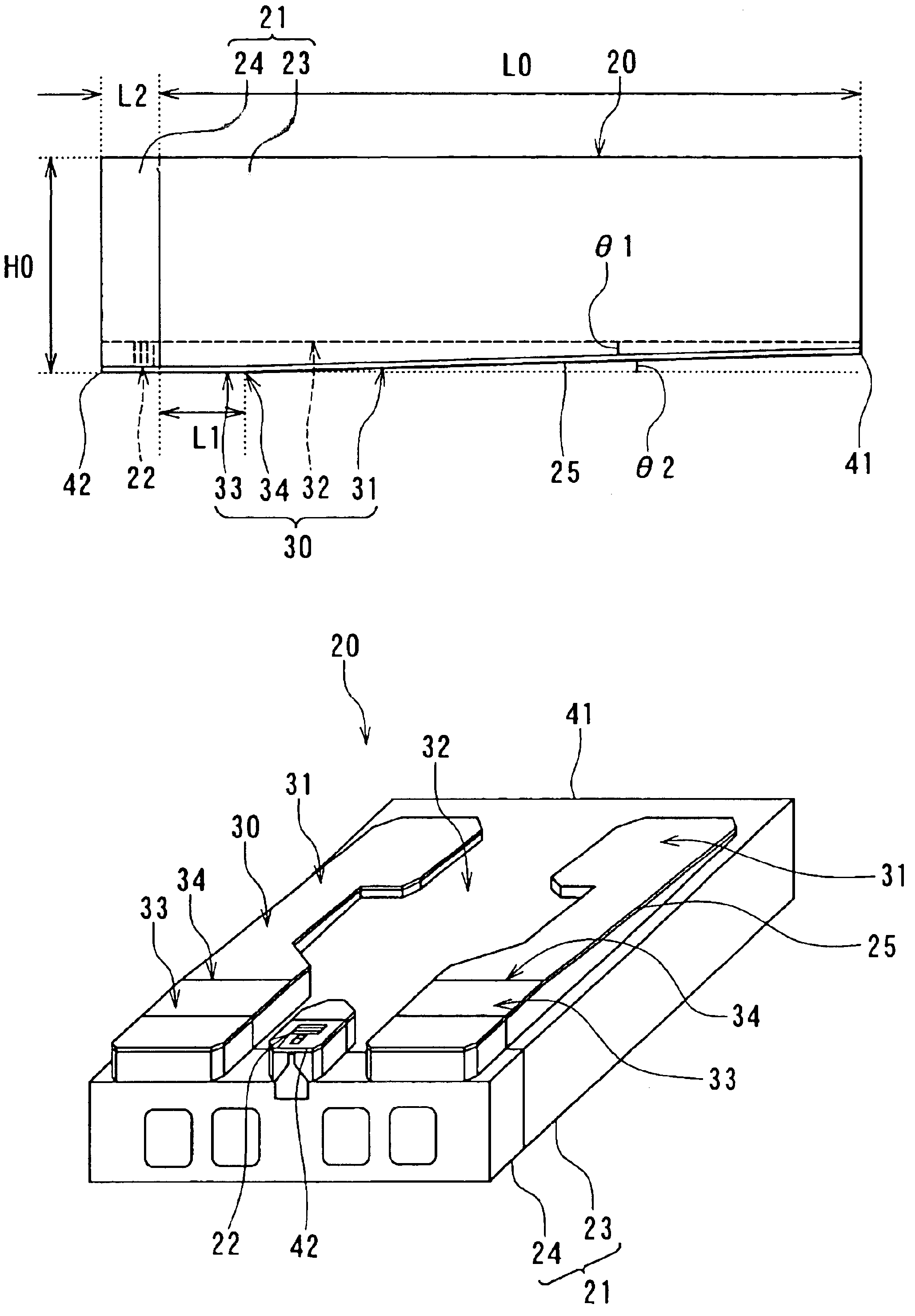
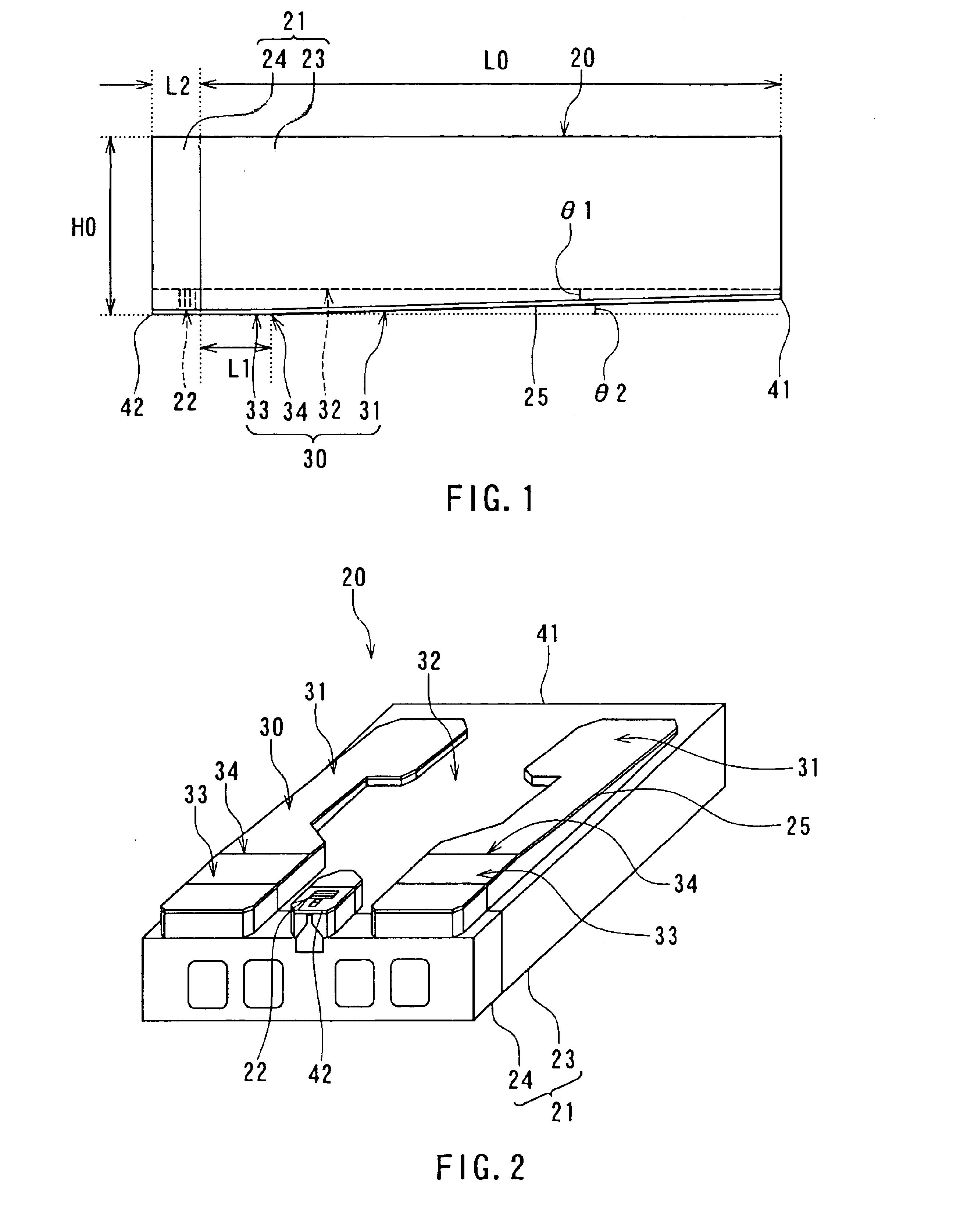
[0117]Reference is now made to FIGS. 1 and 2 to describe a configuration of a slider of a thin-film magnetic head (hereinafter simply referred to as a slider) according to a first embodiment of the invention. FIG. 1 is a side view of the slider according to the embodiment. FIG. 2 is a perspective view of the slider according to the embodiment.
[0118]The slider 20 according to the embodiment comprises a slider body 21 and a thin-film magnetic head element 22. The slider body 21 has: an air bearing surface 30, an air inflow end 41, and an air outflow end 42. The air bearing surface 30 serves as a medium facing surface that faces toward a rotating recording medium. The air inflow end 41 is an end from which an airflow created by the rotation of the recording medium flows in. The air outflow end 42 is an end from which this airflow flows out. The thin-film magnetic head element 22 is disposed near the air outflow end 42 and near the air bearing surface 30 of the slider body 21.
[0119]The ...
second embodiment
[0188]Reference is now made to FIGS. 26 and 27 to describe a method of manufacturing a slider according to a second embodiment of the invention. The slider 20 of the present embodiment has the same configuration as that of the first embodiment. In the method of manufacturing the slider according to the embodiment, as in the first embodiment, a wafer including a plurality of rows of slider portions 50 is initially cut in one direction to form bars each of which includes a row of slider portions 50, as shown in FIG. 13. Each bar has the surface 30A to be the air bearing surfaces 30.
[0189]Then, in this embodiment the surface 30A of the bar is selectively etched to form the second surface 32, as shown in FIG. 26. The etching is performed in the same manner as that for the case of forming the second surface 32 in the first embodiment. The depth of the second surface 32 from the surface 30A is about 2 to 3 μm, for example.
[0190]Then, a step shown in FIG. 27 is performed. In this step, the...
third embodiment
[0194]Reference is now made to FIGS. 28 to 30 to describe a slider according to a third embodiment of the invention. FIG. 28 is a perspective view showing an example of the configuration of the slider according to the embodiment. According to this embodiment, the slider body 21 of the slider 20 makes contact with the surface of the recording medium 45 at the border part 34 of the air bearing surface 30 regardless of whether the recording medium 45 is rotating or at rest.
[0195]As shown in FIG. 28, the slider 20 of the embodiment has a plurality of recesses 35 formed in the air bearing surface 30 in a region including the border part 34. The slider 20 of the embodiment is otherwise configured the same as in the first or second embodiment. According to the slider 20 of the embodiment, since the air bearing surface 30 has the recesses 35 formed in the regions including the border part 34, the area of the slider body 21 contacting the surface of the recording medium 45 becomes smaller th...
PUM
| Property | Measurement | Unit |
|---|---|---|
| angle | aaaaa | aaaaa |
| thickness | aaaaa | aaaaa |
| thickness | aaaaa | aaaaa |
Abstract
Description
Claims
Application Information