Method and apparatus for reducing error recovery time in hard disk drive

Inactive Publication Date: 2005-04-19
MAXTOR
View PDF2 Cites 20 Cited by
  • Summary
  • Abstract
  • Description
  • Claims
  • Application Information

AI Technical Summary

Benefits of technology

[0015]The present invention solves the aforementioned problems and meets the aforementioned, and other, needs. In one embodiment, the invention provides an adaptive error recovery routine for a disk drive which attempts an error recovery step which has an increased probability of recovering an error depending upon previous errors recovered from the disk drive. In one embodiment, the disk drive determines the location of the error, and attempts a first recovery step based on suc

Problems solved by technology

MR elements, however, are not capable of writing to the disk surface.
If the transducer is not within a specific flying height range during the write operation, the number of read errors increases significantly.
If the transitions are weak or the data is not properly “centered” on the track, then the signal to noise ratio (SNR) of the analog read signal will be correspondingly low and poor read performance may result.
Other types of errors may also be present, which are well understood by those of skill in the art.
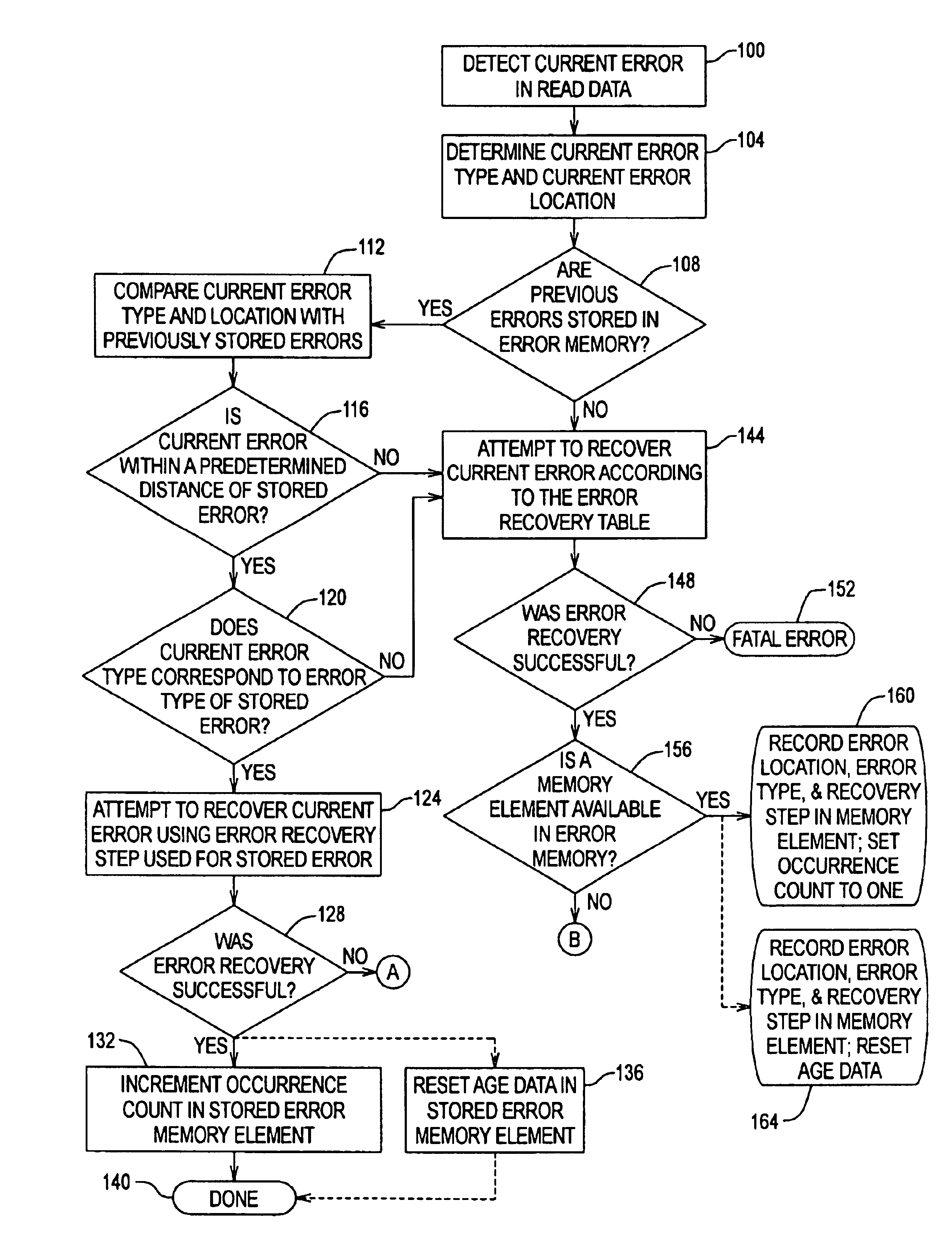
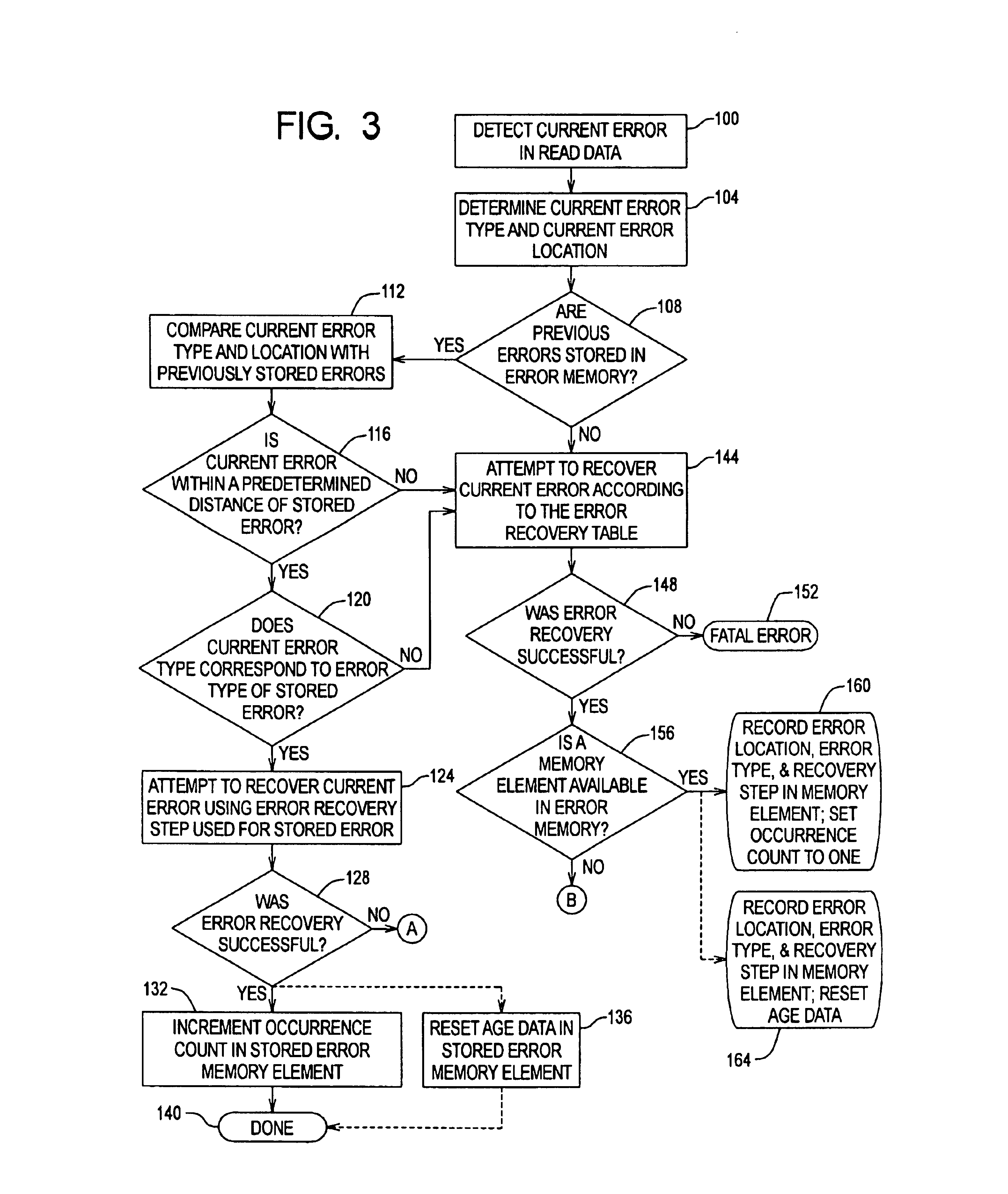
However, if all of the error recovery steps in the error recovery table are attempted with no successful recovery, the disk drive will report a fatal error.
Likewise, the second most common error in the population of disk drives will be the second error recovery step, and so on.
Thus, the time required to reach a step in the table increases the further down the table the error recovery routine needs to go to recover an error.
This testing of disk drives to determine the order of error recovery steps in an error recovery table can take a significant amount of resources to complete.
Even with an error recovery routine which first attempts to recover common errors with respect to the population of disk drives, the error recovery routine may not be enhanced for certain drives.
These outlier drives do not share the same error occurrence frequency as the rest of the population, which results in increased error recovery time as compared to a disk drive that is typical of the population of disk drives.

Method used


Image

  • Method and apparatus for reducing error recovery time in hard disk drive
  • Method and apparatus for reducing error recovery time in hard disk drive
  • Method and apparatus for reducing error recovery time in hard disk drive

Examples


Embodiment Construction

[0025]While this invention is susceptible of embodiments in many different forms, there are shown in the drawings and will herein be described in detail, preferred embodiments of the invention with the understanding that the present disclosure is to be considered as an exemplification of the principles of the invention and is not intended to limit the broad aspects of the invention to the embodiments illustrated.

[0026]FIG. 1 is a block diagram illustrating certain components of a hard disk drive that may be used in connection with the present invention. The hard disk drive 10 includes a magnetic disk 14, an actuator arm 18, and control electronics 22. Within the control electronics 22 are a processor 26 and a memory 30. It will be understood that the processor 26 and memory 30 may be integrated on a single chip, and that, likewise, multiple processors 26 and memories 30 may be present within the control electronics 22. Within the memory 30 is a first storage area 34 which can store ...


PUM


Abstract

An adaptive error recovery routine allows for the recovery from errors in read data of a disk drive. In one embodiment, a disk drive is provided which has an error memory having error memory elements used to record an error type and recovery step for each error recovered from the disk drive. If another error is detected that is of the same type and which is in a location close to a recorded error, the error recovery step used for the previous error is performed for the new error. If the previous error recovery step is not successful, the disk drive performs error recovery using an existing error recovery table, and omits the previous error recovery step.

Description

[0001]Priority is claimed from U.S. Provisional Patent Application No. 60 / 246,383, filed Nov. 7, 2000 entitled “Adaptive Error Recovery,” which is incorporated by reference in its entirety.FIELD OF THE INVENTION[0002]The invention relates generally to digital data storage systems and, more particularly, to recovery from data errors in such systems. The invention is particularly applicable in magnetic data storage systems.BACKGROUND OF THE INVENTION[0003]A disk drive is a digital data storage device that stores digital information within concentric tracks on a storage disk. In magnetic disk drive systems, the storage disk is coated with a magnetic material that is capable of changing its magnetic orientation in response to an applied magnetic field. During operation of a disk drive, the disk is rotated about a central axis at a substantially constant rate. To read data from or write to the disk, a magnetic transducer is centered above a desired track of the disk while the disk is spi...

Claims


Application Information

Patent Timeline
CPCG11B20/18G11B2220/2516G11B2020/183G11B20/1833
Inventor HERMAN, LACE J.MOLINE, JERRY
Owner MAXTOR
Why Eureka
Try Eureka