
Device and method for filling of hydraulic pressure measurement mechanisms

a technology of hydraulic pressure and measurement mechanism, which is applied in the direction of liquid bottling, packaging goods type, packaging under special atmospheric conditions, etc., can solve the problems of contaminating the surface of the filling chamber and the filling, the fill oil no longer meets the oxygen permit specifications, and the effect of reducing the effective suction capacity over the second path

Active Publication Date: 2005-04-26
EHNDRESS KHAUZER GMBKH KO KG
View PDF3 Cites 1 Cited by
  • Summary
  • Abstract
  • Description
  • Claims
  • Application Information

AI Technical Summary

Benefits of technology

[0021]The described method is self-regulating, in so far as the effective suction capacity over the second path is decreased by the evaporation of small amounts of the transfer liquid, which causes the pressure in the filling chamber to rise again and a further evaporation is prevented.

Problems solved by technology

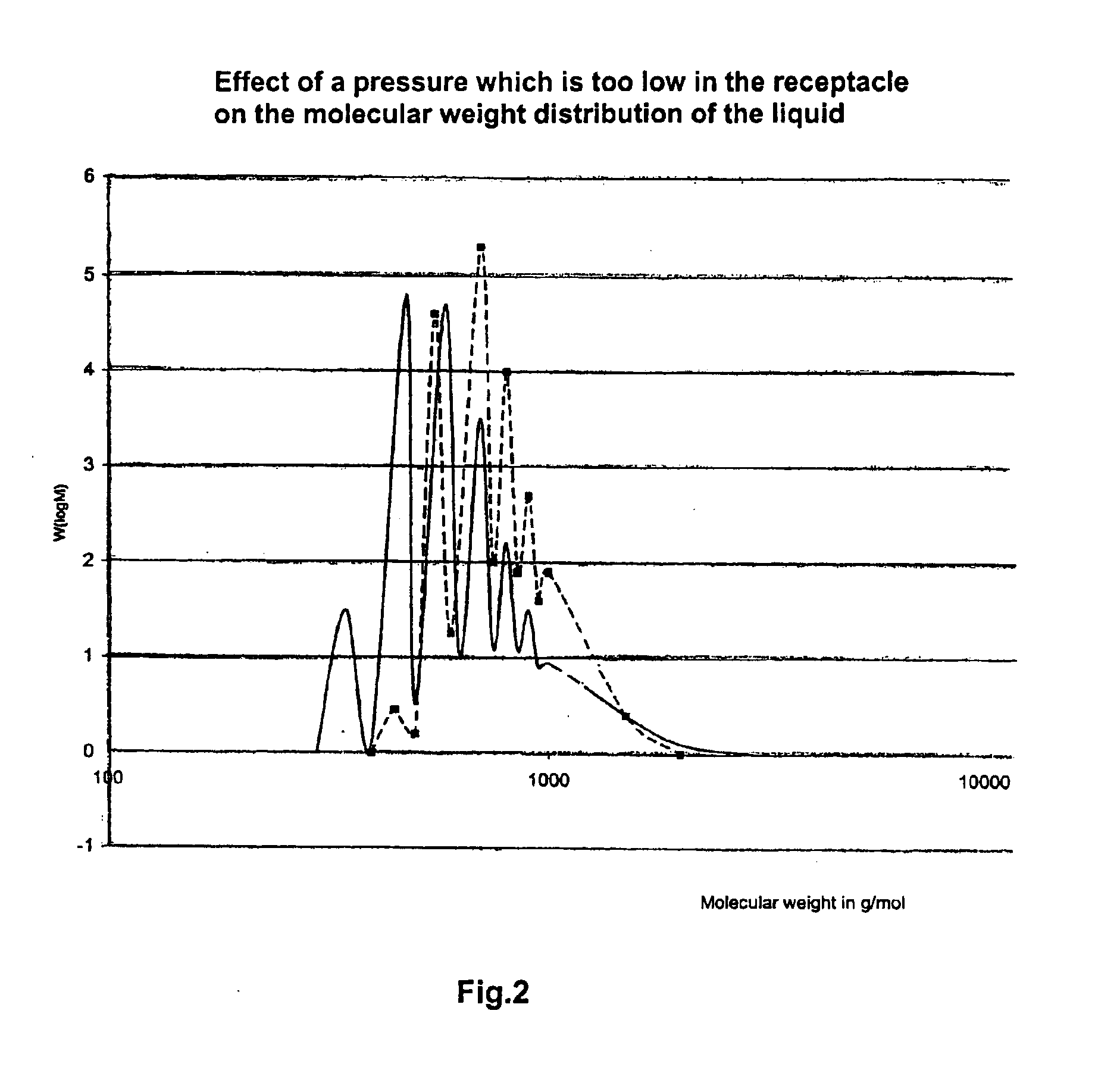
If these fill oils are applied under usual vacuums, for instance −2 torr, then the short-chained components evaporate, which leads to the result that the composition can change to such an extent that the fill oils no longer satisfy the specifications of the oxygen permit.
Thus, the problem concerns not only the fill oils for use in oxygen plants but also, in a certain way, all fill oils which involve a mixture of molecules of different molecular weights.
This technique is disadvantageous in that ambient air enters continuously into the fill chamber to contaminate the surfaces of the fill chamber and the fill liquid e.g. with moisture in the air.

Method used


Image

  • Device and method for filling of hydraulic pressure measurement mechanisms
  • Device and method for filling of hydraulic pressure measurement mechanisms
  • Device and method for filling of hydraulic pressure measurement mechanisms

Examples


Embodiment Construction

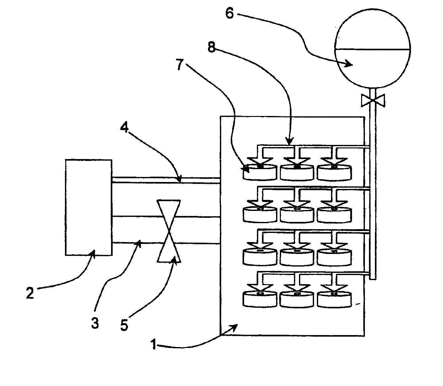
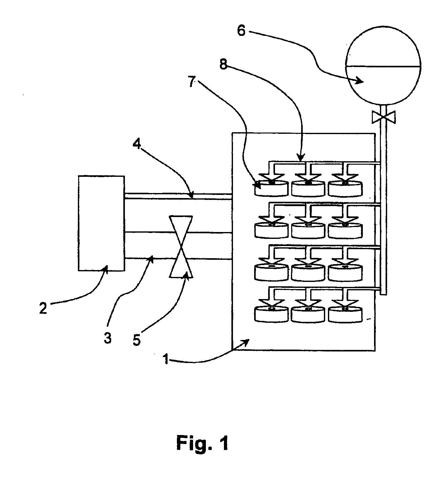
[0032]The device of the invention shown in FIG. 1 includes a filling chamber, or receptacle, 1 to receive the sensors 7 to be filled. The receptacle has a volume of about 10 l and is connected over a line 3 of about 7 cm diameter and about 1 m length with a vacuum pump 2, which preferably is a rotary vane pump. The line 3 is closable by means of a valve 5. In parallel with line 3, a line 4 of about equal length, with a diameter of about 2 mm, extends between the receptacle, or filling chamber 1 and the vacuum pump 2. The receptacle 1 is connected with an oil container 6, by way of suitable taps 8. The oil container is, preferably in a similar manner, kept permanently under vacuum, with the pressure in the oil container preferably being about the equilibrium pressure in the receptacle.

[0033]Following the charging of the receptacle with the measurement mechanisms of the pressure sensors 7, the receptacle is closed and first evacuated through the first suction line 3. Upon reaching the...


PUM

PropertyMeasurementUnit
Pressureaaaaaaaaaa
Pressureaaaaaaaaaa
Pressureaaaaaaaaaa

Abstract

For avoiding the evaporation of volatile components of a fill oil and for avoiding contamination of the fill oil with ambient air, a method for the filling of hydraulic pressure measurement mechanisms by means of a readied filling chamber. The method includes the following steps: (I) Evacuating the filling chamber by means of a vacuum pump over a first path of a first conductivity, extending between the vacuum chamber and the vacuum pump; (II) ending the evacuation of the filling chamber over the first path; (III) continued evacuating of the filling chamber by means of the pump over a second path of a second conductivity, extending between the filling chamber and the vacuum pump, wherein the second conductivity is smaller than the first conductivity; (IV) feeding the fill oil into the evacuated fill chamber and (V) filling the measurement mechanisms.

Description

FIELD OF THE INVENTION[0001]The present invention relates to a device and a method for filling hydraulic pressure- and differential pressure-measurement mechanisms, or other hollow bodies to be filled that have very narrow cavities.BACKGROUND OF THE INVENTION[0002]The measurement mechanisms for absolute pressure, relative pressure and differential pressure using hydraulic pressure transfer exhibit very narrow canals, in order to minimize the required liquid volume. This necessitates, however, a filling of the measurement mechanisms under vacuum. For standard applications, silicone oils having a low vapor pressure are used for the filling, in order that the work can be done at high vacuum without difficulty.[0003]Measurement mechanisms for pressure sensors intended for use in oxygen plants must only be filled with fill liquids which have been specially permitted, in Germany by the Bundesanstalt für Materialprüfung BAM (Federal Institute for Material Testing), and are included in a sp...

Claims


Application Information

Patent Timeline
IPC IPC(8): G01L9/00
CPCG01L19/0645G01L19/0046
Inventor BURCZYK, DIETFRIEDDANNHAUER, WOLFGANGNOTACKER, HARRI
Owner EHNDRESS KHAUZER GMBKH KO KG
Learn More