Stackable heat sink

a heat sink and stacking technology, applied in the field of stackable heat sinks, can solve the problems of high manufacturing cost, high assembly complexity, and poor heat dissipation effect, and achieve the effects of low manufacturing cost, high manufacturing capability, and easy manufacturing

Inactive Publication Date: 2005-04-26
CHI YUAN
View PDF8 Cites 23 Cited by
  • Summary
  • Abstract
  • Description
  • Claims
  • Application Information

AI Technical Summary

Benefits of technology

[0007]It is therefore a primary object of the invention to provide a stackable heat sink for lower manufacturing cost, offer higher manufacturing capability and ease of manufacturing.

Problems solved by technology

Now, a combinational heat sinks are available, the structure consists of many stackable heat dissipation plates, by increasing the numbers of heat dissipation plates to increase the heat dissipation area; however the stacking method is to have those heat dissipation plates sit side by side without sufficient heat dissipation space, the heat dissipation effect is not so good as expected.
Some of the combinational heat sinks besides heat dissipation plates, they also provide a base for assembly: many plugging slots with straight plugging boards, through slots are on the heat dissipation plates for the plugging boards, the plugging boards stabilize the heat dissipation plates, a fastener is pressed on top of the heat dissipation plates, the combination of the plugging boards and the fastener fasten and stabilize the whole structure; however such scheme takes too many components and causes the assembly very complex, all the components need extra tooling to manufacture, the whole manufacturing cost is very high.
However if the heat dissipation plates suffer a external pulling stress, the bendable fastener plate (A4) might bend and depart from the through hole (A2), such structure is not strong enough.

Method used


Image

  • Stackable heat sink
  • Stackable heat sink
  • Stackable heat sink

Examples


Embodiment Construction

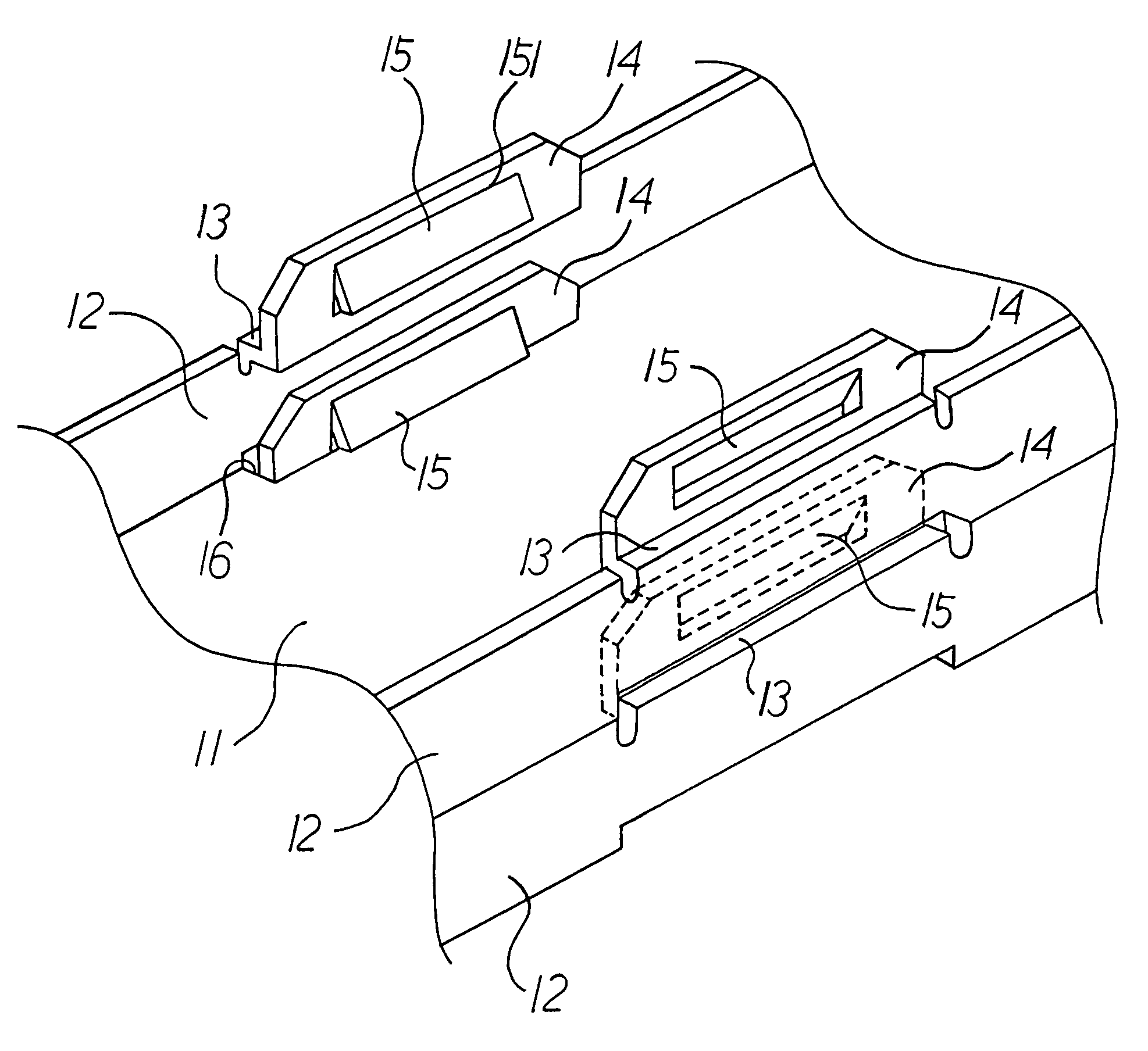
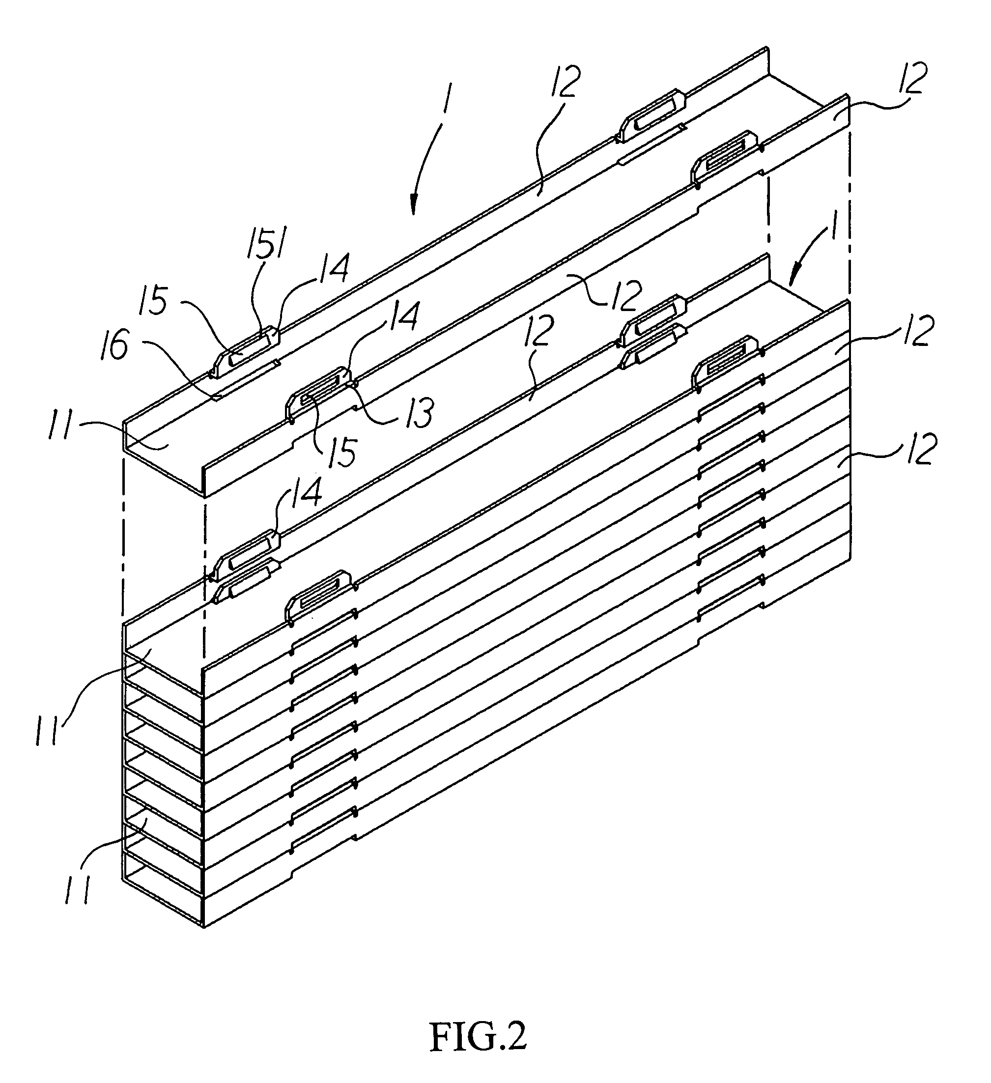
[0017]Referring to FIG. 2 and FIG. 3, the present invention is composed of many stackable heat dissipation plate (1), the heat dissipation plate (1) further composes of a bottom plate (11), two side plate (12) facing each other are on both sides of the bottom plate (11), referring g to FIG. 2, the heat dissipation plate (1) is made from stamping. The side plate (12) bends inward and forms a bending area (13); a standing plate (14) stretches up from the bending area (13) and faces another standing plate (14). A fastening plate (15) is formed on the proper location on the standing plate (14), the fastening plate (15) is a bendable plate; a bending line (151) is on the junction of the standing plate (14) and the fastening plate (15), the bending line (151) stretches vertically to the standing plate (14) to make the fastening plate (15) bendable to the center of the heat dissipation plate (1). A fastening crevice (16) is on the junction of the bottom plate (11), the side plate (12) and...


PUM


Abstract

A stackable heat sink comprising a plurality numbers of metal heat dissipation plates, the heat dissipation plate further comprises a bottom plate, two side plates facing each other locates on both sides of the bottom plate, a bending area is bent from the top of the side plate, two standing plates stretches up from the bending area and facing another standing plate, two fastening plates each is formed on the proper location on the standing plate, the fastening plate is bendable and forms a bending line with the standing plate; two fastening crevices each is located on the junction of the bottom plate and the side plate. When two of the heat dissipation plates stack together, the standing plate of the bottom heat dissipation plate inserts into the fastening crevice of the top heat dissipation plate to make the lower portion of the bending line of the fastening plate fastened on the bottom plate of the top heat dissipation plate, the two heat dissipation plates are fastened closely, a distance is formed between two heat dissipation plates is formed by side plates for heat dissipation.

Description

BACKGROUND OF THE INVENTION[0001]I. Field of the Invention[0002]This invention relates generally to a heat sink and, more specifically, to a stackable heat sink that each heat dissipation plate can fastens and stacks with other heat dissipation plates with certain distance to form heat dissipation gaps, the present invention differs from other heat sinks need plugging boards to be insert into each heat dissipation plate. The top of the heat sink combination is fastener to stable the whole structure; the scheme can lower manufacturing cost, offer higher manufacturing capability and ease of manufacturing.[0003]II. Description of the Prior Art[0004]Heretofore, it is known that most of the heat sinks are made of aluminum by extrusion molding or stamping to have a plurality number of fins in proper distance, the heat is dissipated from the fins with large area to lower the temperature, the one-body structure has a definite shape and specification can be used in certain area, the fins of ...

Claims


Application Information

Patent Timeline
Patent Type & Authority Patents(United States)
IPC IPC(8): H01L23/367H01L23/34
CPCH01L23/3672H01L2924/0002H01L2924/00
Inventor LAI, CHUN-HUNG
Owner CHI YUAN
Why Eureka
Try Eureka