Ac generator for vehicle

a technology for automotive alternators and core construction, applied in the direction of windings, magnetic circuit rotating parts, magnetic circuit shapes/forms/construction, etc., can solve the problems of difficult to avoid resonance in component parts of automotive alternators, high harmonic electromagnetic noise is particularly a problem, and the tone is harsh, so as to achieve the effect of reducing high-speed and low-speed electromagnetic noise and high outpu

Inactive Publication Date: 2005-04-26
MITSUBISHI ELECTRIC CORP
View PDF13 Cites 42 Cited by
  • Summary
  • Abstract
  • Description
  • Claims
  • Application Information

AI Technical Summary

Benefits of technology

[0011]An object of the present invention is to provide an automotive alternator achieving high output by overlapping a laminated core of a stator and yoke portions of a field rotor in an axial direction, and enabling high-speed and low-speed electromagnetic noise to be reduced by prescribing dimensional relationships in the stator and the field rotor.

Problems solved by technology

Noise in automotive alternators can be classified roughly into two groups including wind noise generated by fans and electromagnetic noise, and higher harmonic electromagnetic noise is particularly a problem, being harsh in tone.
It is difficult to avoid resonance in component parts in automotive alternators because the working rotational frequency range is spread over 1,000 to 20,000 revolutions per minute (rpm).
Furthermore, magnetic noise can be reduced by widening the gap between the laminated core and the field rotor to reduce magnetic attraction force, but this countermeasure leads to declines in output.
The generation of this alternating voltage having a disrupted sine wave acts to increase magnetic vibration of the laminated core 51, and one problem has been that low-speed electromagnetic noise is increased by the increased vibration of the stator.
Hence, an alternating voltage having an even more disturbed sine wave is generated, further increasing low-speed electromagnetic noise.
Thus, yet another problem has been that the root portions of the coil end groups and the shoulder portions of the Lundell-type core 52 interfere with each other due to rotation of the Lundell-type core 52, increasing wind noise.

Method used


Image

  • Ac generator for vehicle
  • Ac generator for vehicle
  • Ac generator for vehicle

Examples


embodiment 1

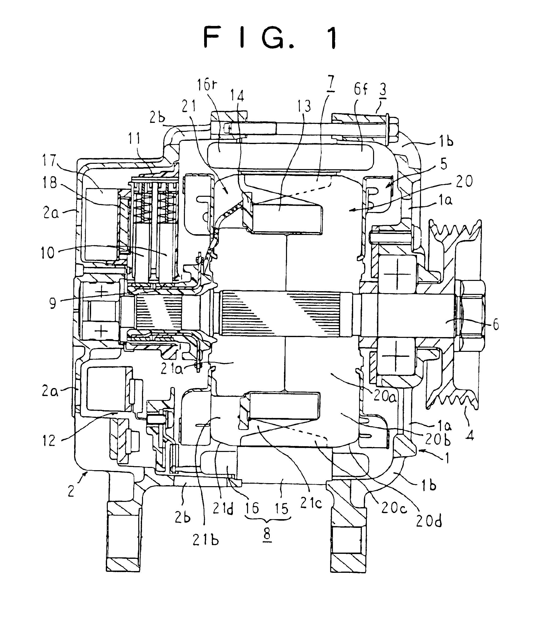
[0036]FIG. 1 is a longitudinal section showing an automotive alternator according to Embodiment 1 of the present invention.

[0037]In FIG. 1, an automotive alternator is constructed by rotatably mounting a field rotor 7 by means of a shaft 6 inside a case 3 constituted by a front bracket 1 and a rear bracket 2 made of aluminum and fixing a stator 8 to an inner wall surface of the case 3 so as to cover an outer circumferential side of the field rotor 7.

[0038]The shaft 6 is rotatably supported in the front bracket 1 and the rear bracket 2. A pulley 4 is fixed to one end of this shaft 6, enabling rotational torque from an engine to be transmitted to the shaft 6 by means of a belt (not shown).

[0039]Slip rings 9 for supplying an electric current to the field rotor 7 are fixed to another end portion of the shaft 6, a pair of brushes 10 being housed in a brush holder 11 disposed inside the case 3 so as to slide in contact with these slip rings 9. A regulator 18 for adjusting the magnitude of...

embodiment 2

[0056]In Embodiment 2, as shown in FIG. 6, ring-shaped covers 24 made of glass-reinforced epoxy resin having a smooth outer surface are disposed so as to cover an inner circumferential side and apex portions of the coil end groups 16f and 16r of the armature coil 16. Moreover, the rest of the construction is constructed in a similar manner to Embodiment 1 above.

[0057]In Embodiment 2, because the covers 24 are disposed so as to cover an inner circumferential side and apex portions of the coil end groups 16f and 16r of the armature coil 16, the covers 24 radially face the shoulder portions 20d and 21d, where pressure fluctuations are greatest in the pole cores 20 and 21.

[0058]Thus, because the coil end groups 16f and 16r, which have irregularities in a circumferential direction, are isolated from the shoulder portions 20d and 21d by the covers 24, wind noise resulting from interference between the coil end groups 16f and 16r and the shoulder portions 20d and 21d arising due to rotatio...

embodiment 3

[0060]In Embodiment 3, as shown in FIG. 7, base portions 5a of the front-end cooling fan 5 are formed into a shape such that valley portions 20e formed between adjacent daw-shaped magnetic pole portions 20c are open in an axial direction. Moreover, the rest of the construction is constructed in a similar manner to Embodiment 1 above.

[0061]Here, at the front end, a cooling airflow is sucked in through the air intake apertures 1a by rotation of the cooling fans 5, and is then deflected centrifugally and discharged outside through the air discharge apertures 1b. On the other hand, at the rear end, a cooling airflow is sucked in through the air intake apertures 2a by rotation of the cooling fans 5, cools the rectifier 12 and the regulator 18, and is then deflected centrifugally and discharged outside through the air discharge apertures 2b. Here, because the rectifier 12 and the regulator 18 are disposed in the ventilation channel for the cooling airflow at the rear end, ventilation resi...


PUM


Abstract

An object of the present invention is to provide an automotive alternator achieving high output by overlapping a laminated core of a stator and yoke portions of a field rotor in an axial direction, and enabling high-speed and low-speed electromagnetic noise to be reduced by prescribing dimensional relationships in the stator and the field rotor.
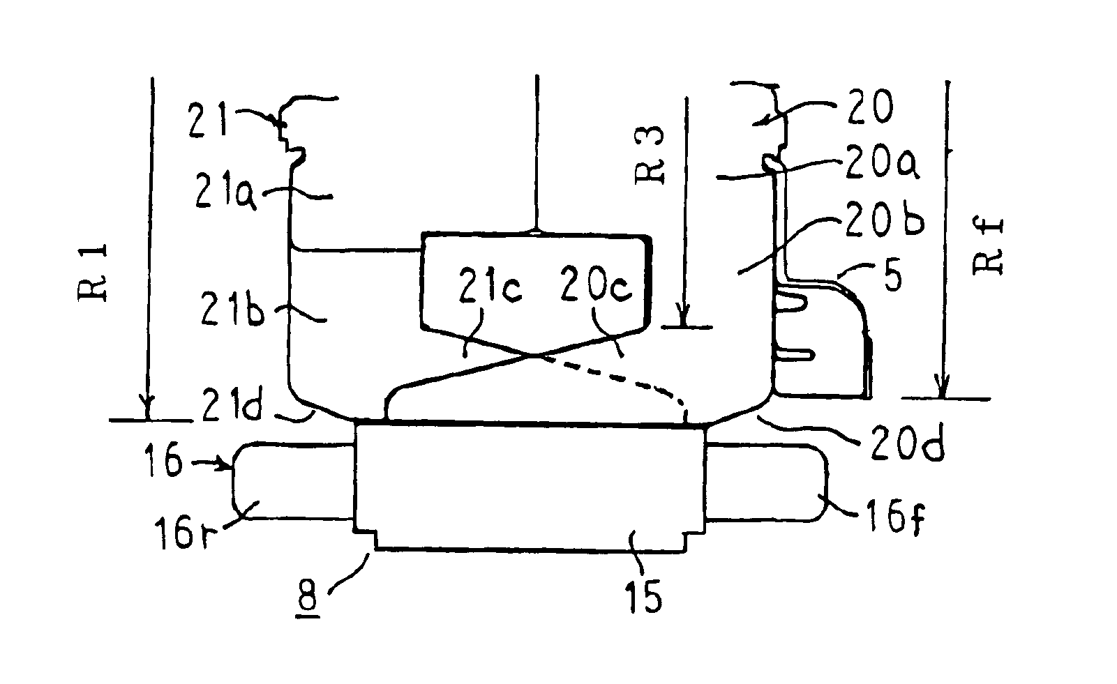
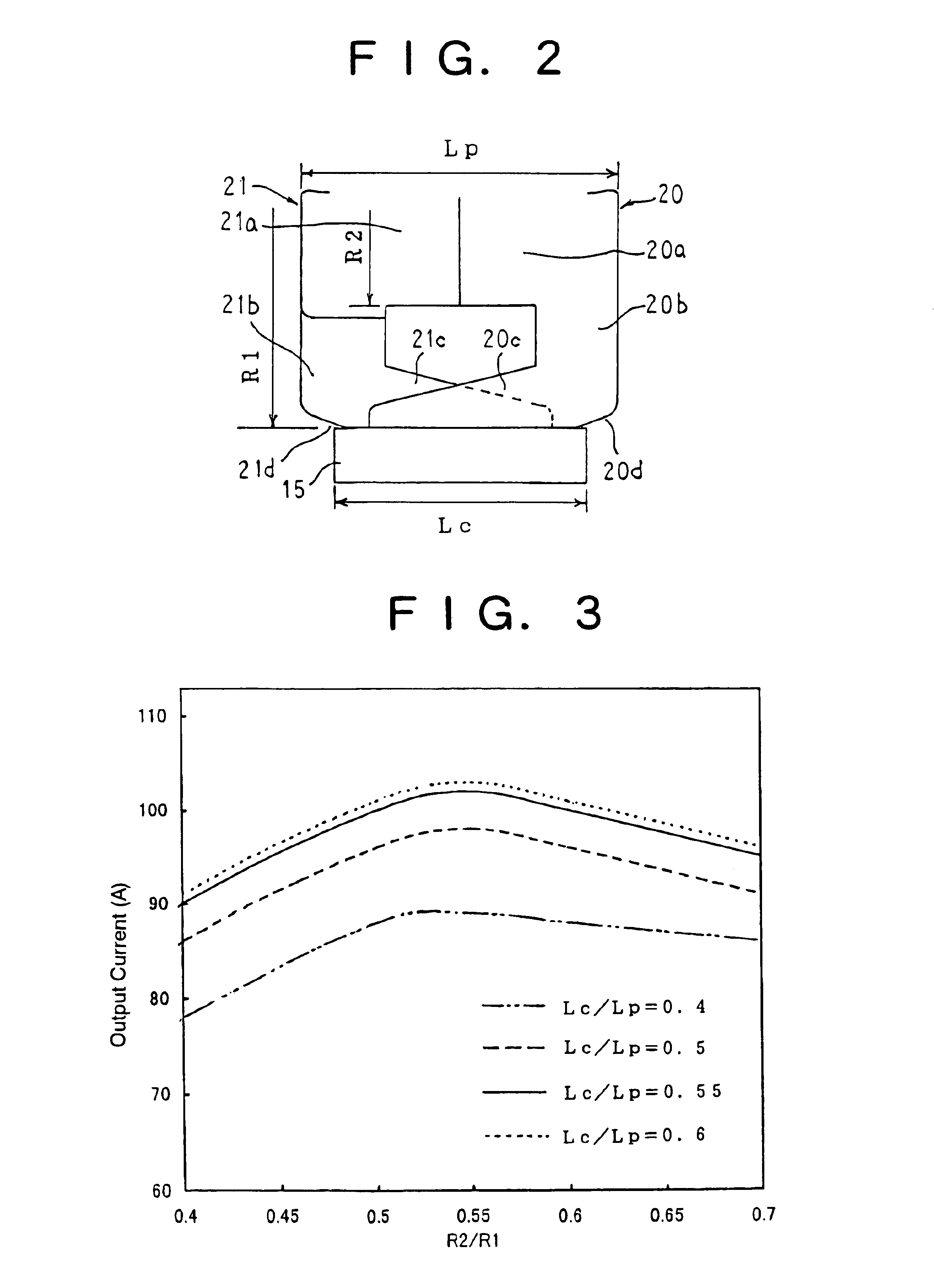
In this automotive alternator, a ratio (R2/R1) between an outer radius R2 of a cylindrical portion of a Lundell-type core and an outer radius R1 of the Lundell-type core is set to a range from 0.50 to 0.54, and a ratio (Lc/Lp) between an axial length Lc of the laminated core and an axial length Lp of the Lundell-type core is set to a range from 0.55 to 0.70.

Description

TECHNICAL FIELD[0001]The present invention relates to an automotive alternator, and particularly to a Lundell-type core construction of an automotive alternator enabling claw resonance noise generated by magnetic attraction force acting on claw-shaped magnetic poles to be reduced by improving the magnetic balance of magnetic attraction force.BACKGROUND ART[0002]In recent years, due to noise reduction in engines and the accompanying reduction of sound insulation equipment, the lowering of noise in automotive alternators mounted to the engines is in demand. Noise in automotive alternators can be classified roughly into two groups including wind noise generated by fans and electromagnetic noise, and higher harmonic electromagnetic noise is particularly a problem, being harsh in tone.[0003]Generally, it is known that magnetic attraction force proportional to rotational frequency is generated in automotive alternators in air-gap portions between claw-shaped magnetic pole portions of a fi...

Claims


Application Information

Patent Timeline
Patent Type & Authority Patents(United States)
IPC IPC(8): H02K9/06H02K1/22H02K1/24H02K9/04H02K19/22H02K19/16
CPCH02K1/243H02K19/22H02K9/06H02K5/24
Inventor OOHASHI, ATSUSHIASAO, YOSHIHITOADACHI, KATSUMI
Owner MITSUBISHI ELECTRIC CORP
Why Eureka
Try Eureka