Method and device for cooling high voltage transformer for microwave oven

a high-voltage transformer and microwave oven technology, which is applied in fixed transformers, transformers/inductances magnetic cores, electric/magnetic/electromagnetic heating, etc., can solve the problems of difficult miniaturization, increased equipment for manufacturing high-voltage transformers, and complicated high-voltage transformers

Inactive Publication Date: 2005-04-26
PURETEC
View PDF4 Cites 15 Cited by
  • Summary
  • Abstract
  • Description
  • Claims
  • Application Information

AI Technical Summary

Benefits of technology

[0021]In accordance with yet another aspect of the present invention, there is provided a device for cooling a high voltage transformer for a microwave oven, comprising: a container for accommodating the high voltage transformer; corrugated portions with concave portions and convex portions, formed in a regular arrangement on each of side surfaces of a case of the container so as to more rapidly cool a cooling oil absorbing heat conducted thereto by

Problems solved by technology

In case the high voltage transformer is manufactured by passing through the aforementioned impregnation step, the process for manufacturing the high voltage transformer is complicated and consequently equipment for manufacturing the high voltage transformer is increased in size.
Further, since, in the high voltage transformer manufactured by passing through the impregnation step, the heat generated from the coil is not conducted to the core or the outside, the high voltage transformer is disadvantageous that it is difficult to miniaturize.
The aforementioned high voltage tra

Method used


Image

  • Method and device for cooling high voltage transformer for microwave oven
  • Method and device for cooling high voltage transformer for microwave oven
  • Method and device for cooling high voltage transformer for microwave oven

Examples


first embodiment

[0042]FIG. 3 is a perspective view of a device for cooling a high voltage transformer for a microwave oven in accordance with the present invention. FIG. 4 is a perspective view of the device for cooling the high voltage transformer for the microwave oven, taken along the line A—A, of FIG. 3, and FIG. 5 is a cross-sectional view of the device for cooling the high voltage transformer for the microwave oven, taken along the line B—B, of FIG. 3. FIG. 6 is a cross-sectional view showing another example of a terminal for leading an electric connection line of the device for cooling the high voltage transformer for the microwave oven of FIG. 3. FIG. 7 is a broken-away perspective view showing another example of a container applied to the device for cooling the high voltage transformer for the microwave oven of FIG. 3, and FIG. 8 is a broken-away perspective view showing yet another example of a container applied to the device for cooling the high voltage transformer for the microwave oven...

fourth embodiment

[0056]FIG. 9 is a partially broken-away perspective view of a device for cooling a high voltage transformer for a microwave oven in accordance with a second embodiment of the present invention. FIG. 10 is a cross-sectional of the device for cooling the high voltage transformer for the microwave oven, in which inner components are omitted, taken along the line C—C, of FIG. 9. FIG. 11 is an enlarged cross-sectional view of an example of the portion D of the device for cooling the high voltage transformer for the microwave oven of FIG. 9, and FIG. 12 is an enlarged cross-sectional view of another example of the portion D of the device for cooling the high voltage transformer for the microwave oven of FIG. 9. FIG. 13 is an enlarged cross-sectional view of an example of the portion E of the device for cooling the high voltage transformer for the microwave oven of FIG. 9, and FIG. 14 is an enlarged cross-sectional view of another example of the portion E of the device for cooling the high...

second embodiment

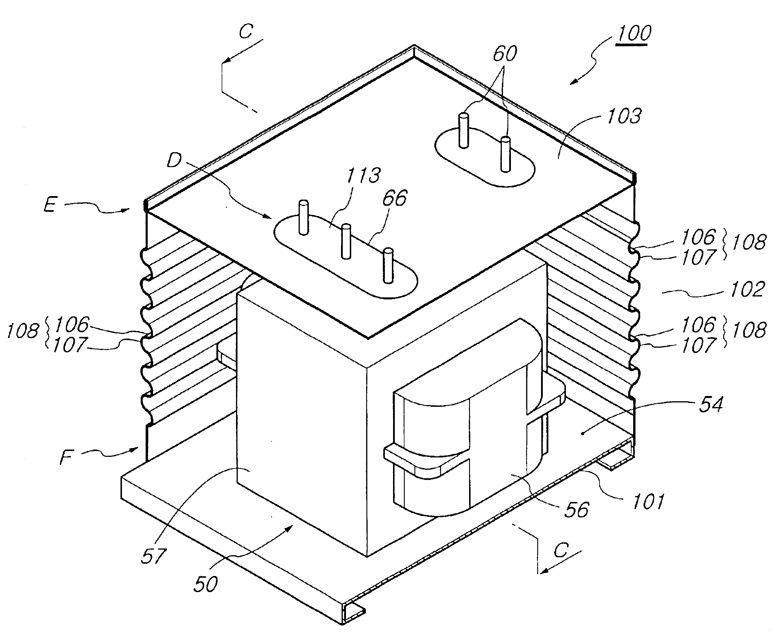
[0057]In accordance with the present invention, there is provided a device for cooling the high voltage transformer 50 by inserting the high voltage transformer 50 into the container 51 so as to more easily cool the cooling oil 54 absorbing the heat of a high temperature generated from the coil 56 and the core 57, to more effectively treat the electric connection lines 60 leading from the high voltage transformer 50, and to improve a fixed structure of the container 51.

[0058]For this purpose, the container 51 comprises a base 101, a case 102, and a cover 103. Corrugated portions 108 with concave portions 106 and convex portions 107 in a semicircular shape are formed on each of side surfaces of the case 102 of the container 51, thereby more rapidly cooling the cooling oil 54 absorbing the conducted heat by convection current.

[0059]Instead of the aforementioned semicircular shape, each of the corrugated portions 108 may have various shapes such as rectangle, triangle, etc., as long as...


PUM


Abstract

Disclosed are a method and a device for cooling a high voltage transformer for a microwave oven, in which the high voltage transformer is sealed so as to separate a coil and a core from the outside and to improve a cooling effect, and in which electric connection lines leading from the high voltage transformer are effectively treated and a fixed structure of a container for accommodating the high voltage transformer is improved so as to protect users of the high voltage transformer from dangers such as an electrical shock occurring in inspecting the microwave oven, thereby improving performance and quality of the microwave oven and the high voltage transformer. The method for cooling the high voltage transformer for the microwave oven comprises the steps of: inserting the high voltage transformer into a container with a designated size and sealing the container; injecting a cooling oil into the container so as to absorb heat of a high temperature generated from a coil and a core of the high voltage transformer; and cooling the cooling oil absorbing the heat by radiating the heat via the container exchanging the heat with the outside.

Description

BACKGROUND OF THE INVENTION[0001]1. Field of the Invention[0002]The present invention relates to a method and a device for cooling a high voltage transformer for a microwave oven, and more particularly to a method and a device for cooling a high voltage transformer for a microwave oven so as to rapidly remove heat generated from a coil and a core in the operation of the high voltage transformer, thereby improving performance and quality of the microwave oven and the high voltage transformer.[0003]2. Description of the Related Art[0004]Generally, high voltage transformers are used in electronic appliances for preparing food using a high frequency, such as microwave ovens. The high voltage transformer is a kind of a power feed unit, which heats a heater of a magnetron for generating high frequency microwave and simultaneously constitutes a half-wave voltage doubler circuit, thereby applying high voltage of 4,000V to the magnetron via a condenser so that the magnetron generates the hig...

Claims


Application Information

Patent Timeline
IPC IPC(8): H01F27/12H01F27/26H01F27/10H05B6/66H01F27/04H01F38/00H01F38/08H01F27/02H05B6/64H01F30/00
CPCH01F27/12H05B6/662H01F27/266H01F27/025H01F27/04H01F38/08H01F2038/003
Inventor CHOI, BU-SIK
Owner PURETEC
Why Eureka
Try Eureka