
Telecommunications network

Inactive Publication Date: 2005-04-26
VERIZON PATENT & LICENSING INC
View PDF40 Cites 56 Cited by
  • Summary
  • Abstract
  • Description
  • Claims
  • Application Information

AI Technical Summary

Benefits of technology

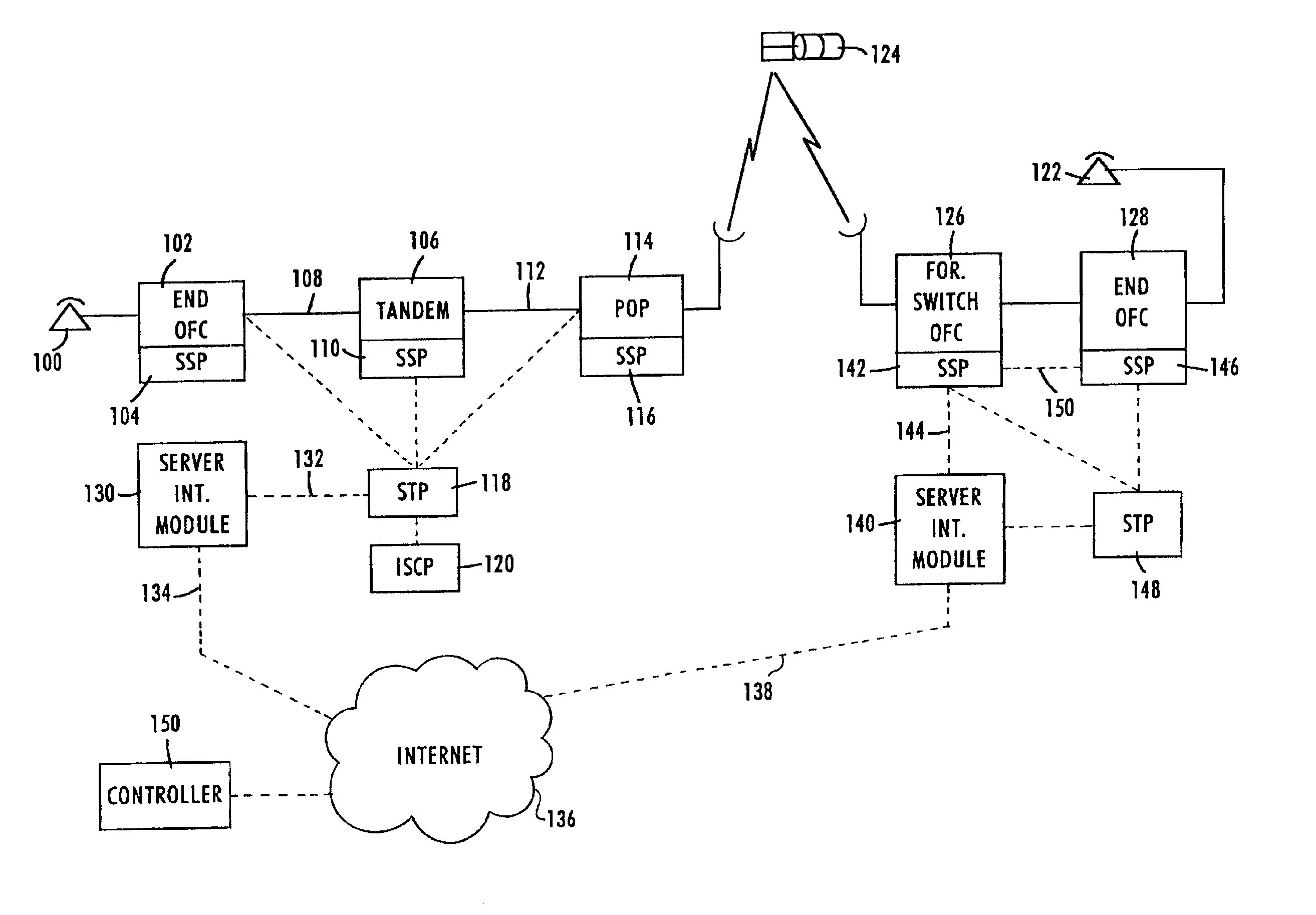
[0095]It is an object of the present invention to provide telephone service over wide areas between different telephone systems and carriers using a new form of common channel signaling architecture which permits use of existing telecommunication signaling control facilities in conjunction with existing and readily available world wide connectionless data networks.

Problems solved by technology

Although generally known, use of several of these acronyms is not strictly standardized in the art.
The simplest protocols define only a hardware configuration, while more complex protocols define timing, data formats, error detection and correction techniques and software structures.
There is no central backbone master device to grant requests to gain access to the backbone.
While this type of multipoint topology facilitates rapid transmission of data when the backbone is lightly utilized, packet collisions may occur when the backbone is heavily utilized.
While this topology reduces data collisions, the latency incurred while each node waits for the token translates into a slower data transmission rate than Ethernet when the network is lightly utilized.
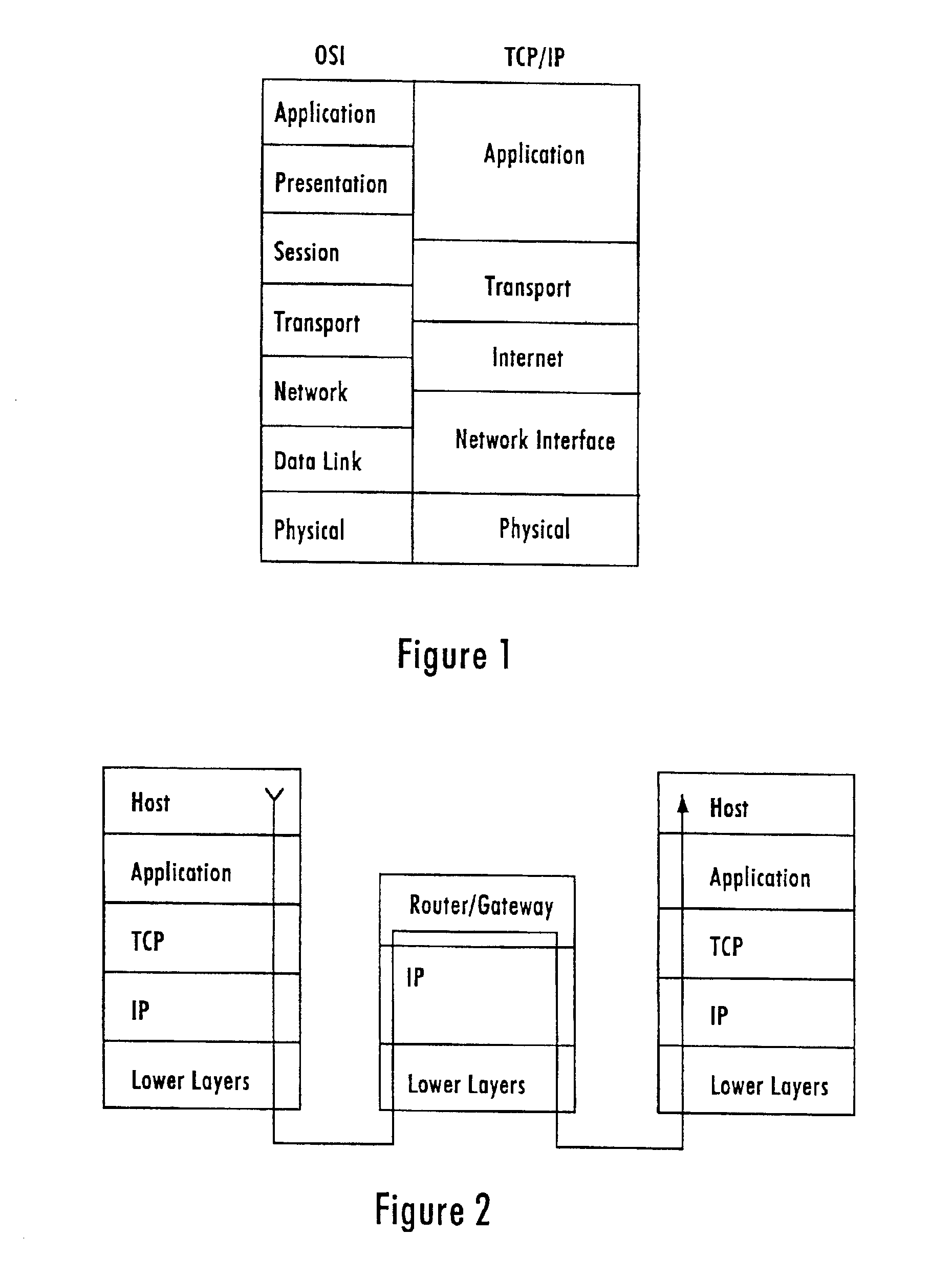
Some of these approaches have emerged as de facto standards, but there is still no single standard for network communication.
As network topologies become more complex, with large numbers of LANs, and multiple bridges interconnecting them, operational difficulties can ensue if all possible LAN bridging connections are permitted.
In the worst case, messages will be duplicated to such a degree that the networks will be effectively clogged with these messages and unable to operate at all.
In addition, the IP does not provide for error reporting back to the source when routing anomalies occur.
In-band signaling, however, tends to be relatively slow and ties up full voice channels during the signaling operations.
In telephone call processing, a substantial percentage of all calls go unanswered because the destination station is busy.
In-band signaling also is highly susceptible to fraud because hackers have developed devices which mimic in-band signaling.
Also, messages from the end users always utilize an in-band format and remain in-band, making it virtually impossible for an end user to simulate signaling messages which ride on an out-of-band channel or network.
However, such control is not available in the United States on a nationwide basis and is not available internationally for a variety of reasons.
This requires inefficient use of circuit time of voice trunks and is vulnerable to fraud.

Method used


Image

  • Telecommunications network
  • Telecommunications network
  • Telecommunications network

Examples


Embodiment Construction

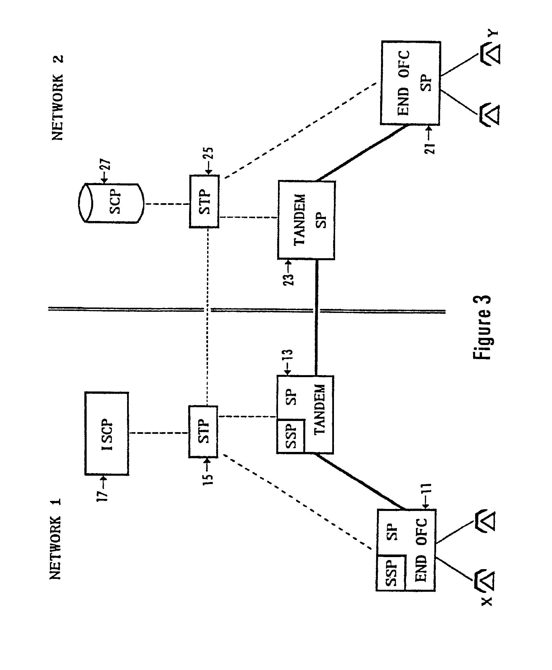
[0116]To facilitate understanding of the present invention, it will be helpful first to review the architecture and operation of a telephone network having CCIS capabilities.

[0117]Referring to FIG. 3 there is shown a simplified block diagram of a switched traffic network and the common channel signaling network used to control the signaling for the switched traffic network. In the illustrated example, the overall network actually comprises two separate networks 1 and 2. As shown, these networks serve different regions of the country and are operated by different local exchange carriers. Alternatively, one network may be a local exchange carrier network, and the other network may comprise an interexchange carrier network. Although the signaling message routing of the present invention will apply to other types of networks, in the illustrated example, both networks are telephone networks.

[0118]In FIG. 3, a first local exchange carrier network 1 includes a number of end office switchin...


PUM


Abstract

A system and method for controlling on a worldwide basis two or more telecommunications networks which are themselves capable of exercising a form of common channel signaling network control. The system uses an architecture in which a destination telecommunications network having common channel signaling control is connected to an originating telecommunications network having common signaling control through a call set up and control methodology which provides ad hoc connection between the two spaced telecommunication networks and common channel signaling networks via an unrelated world wide data network which preferably constitutes the Internet.

Description

[0001]Application Ser. No. 09 / 291,037 filed on Apr. 14, 1999 now U.S. Pat. No. 6,625,170. This application is also related to application Ser. No. 09 / 584,691 filed Jun 1, 2000 which is a continuation of Application number 09 / 291,037 filed on Apr. 14, 1999.TECHNICAL FIELD[0002]The present invention relates to a telecommunications network and more particularly relates to a public switched telecommunications network having a control signaling system which provides wide area national and international routing and supervision using out of band signaling which includes a virtual common channel signaling system which does not require an end to end exchange of data messages using a connection oriented mode of signaling. The following background material introduces various telephone network control and computer network concepts and definitions and those familiar with telephone network control and computer networks and TCP / IP may wish to skip to following subsections.Acronyms[0003]The written...

Claims


Application Information

Patent Timeline
IPC IPC(8): H04L12/24H04Q3/00H04M7/00H04M7/06
CPCH04L12/24H04M7/00H04Q3/0045H04L41/00H04Q2213/13405H04M3/42102H04M3/42365H04Q2213/1302H04Q2213/1304H04Q2213/13093H04Q2213/13097H04Q2213/13103H04Q2213/13106H04Q2213/13196H04Q2213/13204H04Q2213/13216H04Q2213/13292H04Q2213/13333H04Q2213/13345H04Q2213/13383H04Q2213/13389
Inventor CURRY, JAMES E.FARRIS, ROBERT D.
Owner VERIZON PATENT & LICENSING INC
Learn More