Multiple-exposure drawing apparatus and method thereof

a drawing apparatus and exposure unit technology, applied in the direction of photomechanical apparatus, printing, instruments, etc., can solve the problems of complex machine control, limited flexibility of circuit pattern design, and increased number of elements

Active Publication Date: 2005-04-26
ORC MFG
View PDF6 Cites 33 Cited by
  • Summary
  • Abstract
  • Description
  • Claims
  • Application Information

AI Technical Summary

Problems solved by technology

Thus, flexibility of circuit pattern design is restricted by the drawing apparatus.
Thereby, the number of elements is increased, so that complex machine control is required and this may induce failure.
Furthermore, when a str

Method used


Image

  • Multiple-exposure drawing apparatus and method thereof
  • Multiple-exposure drawing apparatus and method thereof
  • Multiple-exposure drawing apparatus and method thereof

Examples


Embodiment Construction

[0031]The present invention is described below with reference to the embodiments shown in the drawings.

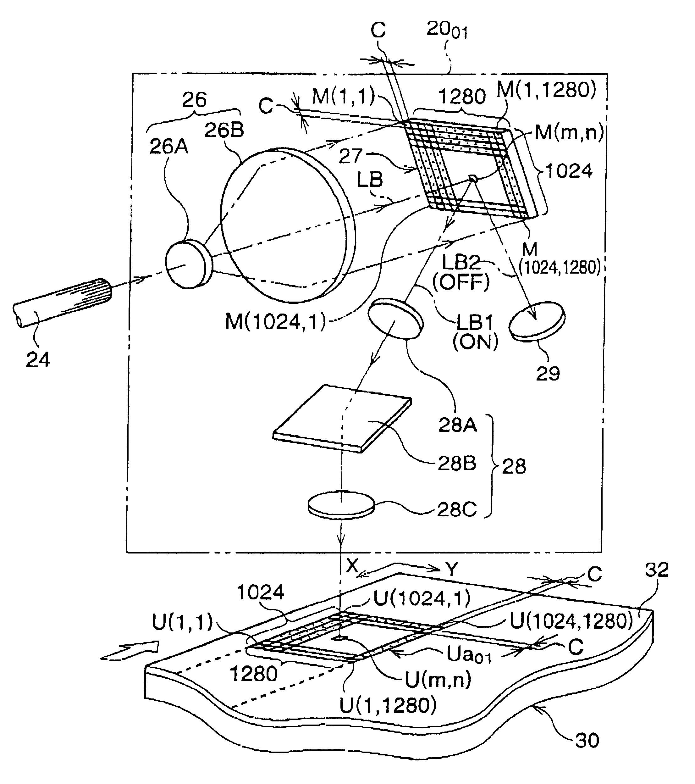
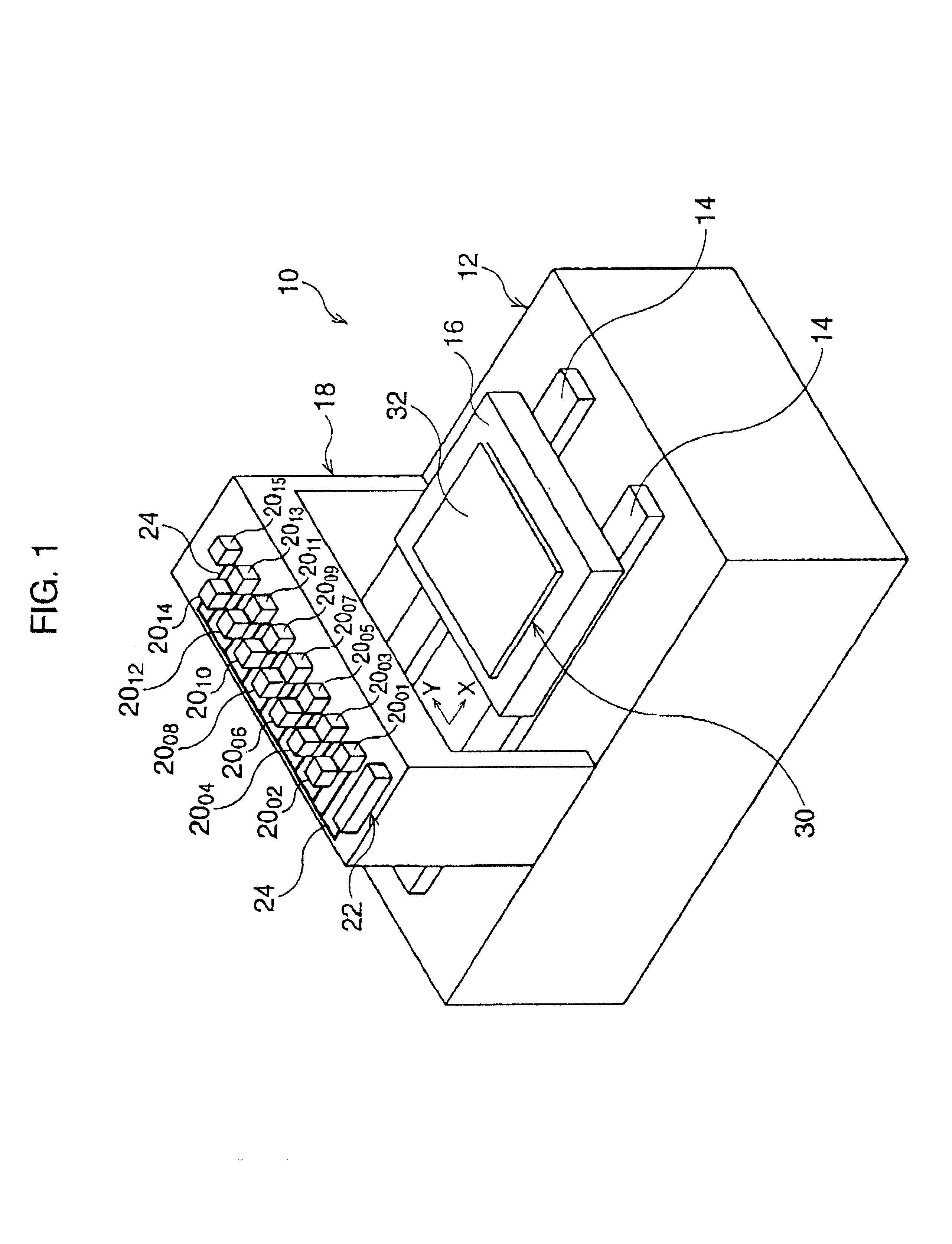
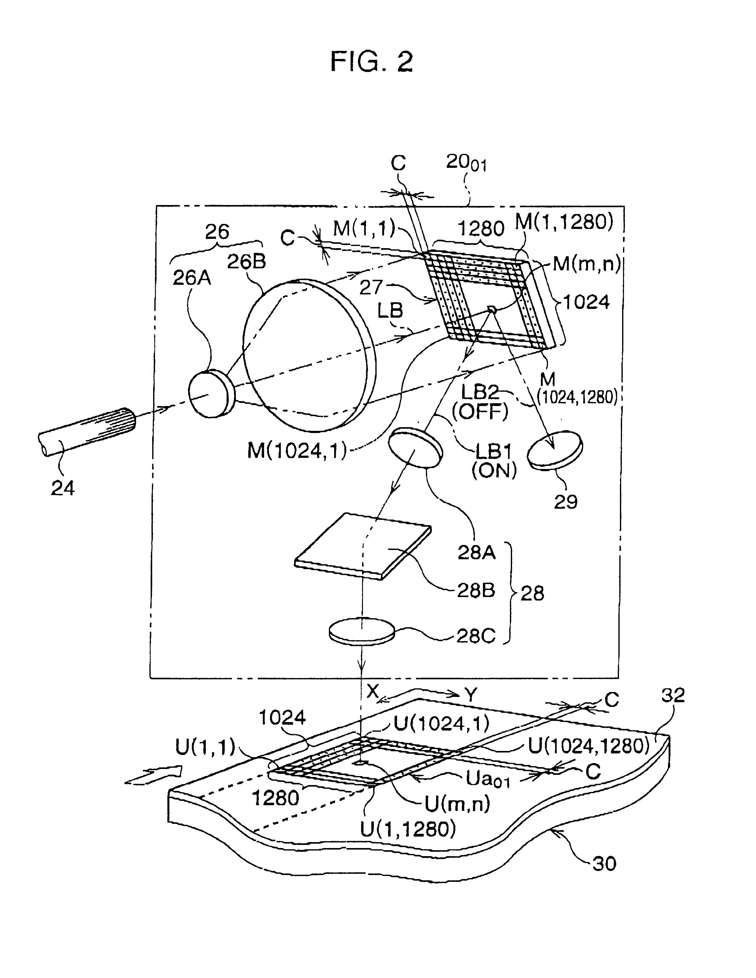
[0032]FIG. 1 schematically and perspectively shows an embodiment of the multi-exposure drawing apparatus according to the present invention. The multi-exposure drawing apparatus is constituted to directly draw a circuit pattern on a photoresist layer formed on a suitable substrate, for manufacturing a printed circuit board.

[0033]As shown in FIG. 1, the multi-exposure drawing apparatus 10 comprises a base structure 12 installed on a floor. A pair of guide rails 14 is laid on the base structure 12 in parallel, and a drawing table 16 is movably placed on the pair of guide rails 14. Although not illustrated in FIG. 1; the drawing table 16 is relatively moved along the pair of guide rails 14, or along the longitudinal direction X, by a drive motor, such as a stepping motor, a servo motor or the like through a suitable drive mechanism, such as a. ball-screw mechanism. A workpiece 30 havi...


PUM


Abstract

A multi-exposure drawing apparatus for drawing a given pattern on a workpiece is provided. The apparatus uses an exposure unit with optical modulation elements arranged in a matrix. The apparatus comprises a first, second, and third memory, a coordinate transformation processor, a calculation processor, and an exposure-data generating processor. The first, second, and third memory respectively stores raster-data of the given pattern, first-coordinate data representing a position of each optical modulation element, and second-coordinate data representing a position of the exposure unit. The coordinate transformation is performed for the first-coordinate data. Address-data is calculated in accordance with a pixel size of the raster-data, and is based on the sum of the first and second coordinate data. Exposure-data generated by outputting the raster-data of the address-data is given to each of the optical modulation elements. The given pattern is drawn on the drawing surface as to the exposure-data.

Description

BACKGROUND OF THE INVENTION[0001]1. Field of the Invention[0002]The present invention relates to a method and a drawing apparatus with an exposure unit that includes a plurality of modulation elements arranged in a matrix, for producing patterns on a surface of a workpiece.[0003]2. Description of the Related Art[0004]The above drawing apparatus is generally used to produce minute and fine patterns, characters, symbols, and so on, on suitable workpieces by an optical method. An example of a use of the drawing apparatus is for a circuit pattern drawn on a workpiece when a printed circuit board is manufactured by using photolithography. The workpiece may be either a photosensitive film for producing a photomask or a photoresist layer formed on a suitable substrate.[0005]In recent years, the entire circuit board production process, from the circuit-board pattern designing process to the image-producing process, has been integrated and systematized into an integrated system in which a dr...

Claims


Application Information

Patent Timeline
IPC IPC(8): G03F7/20G03B27/53G03B27/54G03F9/00G06F19/00H05K3/00
CPCG03F7/2057
Inventor OKUYAMA, TAKASHI
Owner ORC MFG
Why Eureka
Try Eureka