Moisture removal system

Inactive Publication Date: 2005-05-03
INJECTIDRY SYST
View PDF12 Cites 13 Cited by
  • Summary
  • Abstract
  • Description
  • Claims
  • Application Information

AI Technical Summary

Benefits of technology

[0011]The manner of distribution of the air however, is completely new and improved in several respects. First, much smaller penetration holes can be used with the improved injectors. The new injectors are smaller than in previous systems, and yet have means for preventing accidental withdrawal. Specifically, each injector has locking tabs which can be depressed by the fingers of the user to reduce the effective diameter of the injector to facilitate insertion of the injector into the small hole. Once the injector is inserted however, the tabs can be released, and they will spring back into place, creating an effective diameter that is wider than the hole into which the injector was inserted, thereby preventing accidental withdrawal of the injector. This feature is particularly helpful in positive pressure mode, when the mere force of the air emanating from the injector will tend to dislodge the injector from the hole. It is also particularly helpful when drying ceilings, where the force of gravity tends to pull the injector out of the hole. This locking tab mechanism can also be easily removed without any damage to even fragile structures simply by re-pressing the tabs, and pulling. The locking tab mechanism is a significant improvement over the prior systems, some of which relied either on fletchings or threads and friction (which required a larger injector diameter and hence a larger penetration hole and tended to result in damage around the edge of the hole in any case), and others of which lacked the friction fletchings and the larger hole, and were of small diameter, but which were not effective in preventing accidental withdrawal. Also, the locking tab mechanism makes it extremely easy to quickly and install and remove the injectors with zero damage to the structure other than the very small hole. The locking tab mechanism is not only much easier to use than the threaded or fletched injectors, but causes less damage. In the preferred embodiment a pair of opposing locking tabs are utilized, but either one or any number of tabs may be used in accordance with the invention.
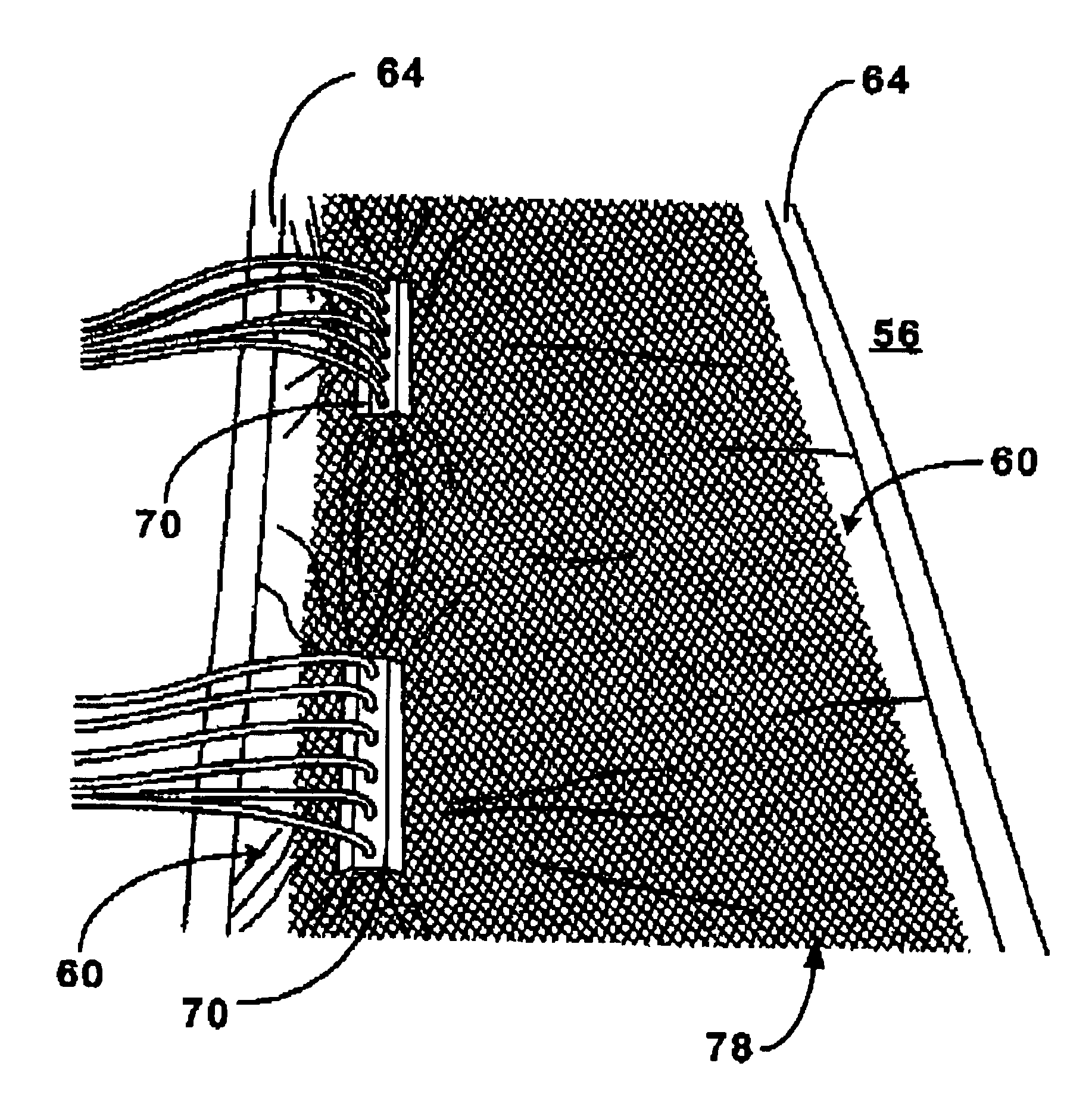
[0018]The next step will be to set up a blower, such as an Injectidry HP 60 or 90, set on the suction side (negative pressure mode). Next, the tubes are connected from the standard blower to the barbs on the vacuum plates. When the system is thus set up, the blower is activated, and the covered floor area will begin drying. In appearance, the system will resemble a “shrink wrapped” floor section. Importantly, because of the configuration of the grid and the vacuum plate, the impermeable membrane such as visqueen, although taped or otherwise sealed around its perimeter, and compressed by negative pressure against the grid, will not prevent the migration of air or water from the floor, up through the two planes of the grid, into the vacuum plate and thence out through the tubes to the blower. While this system is effective at drying floors, it is also useful in removing excess moisture entrapped in fiberglass or wooden boat hulls.

Problems solved by technology

The locking tab mechanism is a significant improvement over the prior systems, some of which relied either on fletchings or threads and friction (which required a larger injector diameter and hence a larger penetration hole and tended to result in damage around the edge of the hole in any case), and others of which lacked the friction fletchings and the larger hole, and were of small diameter, but which were not effective in preventing accidental withdrawal.
While this arrangement had advantages over prior systems, it also had practical disadvantages.
Specifically, it had a tendency to clog, especially when drying sheetrock enclosed cavities, or other structural cavities with debris therein.
Thus, if the hole at the end of the injector becomes plugged or clogged, the air may still be drawn in through the slot.

Method used


Image

  • Moisture removal system
  • Moisture removal system
  • Moisture removal system

Examples


Embodiment Construction

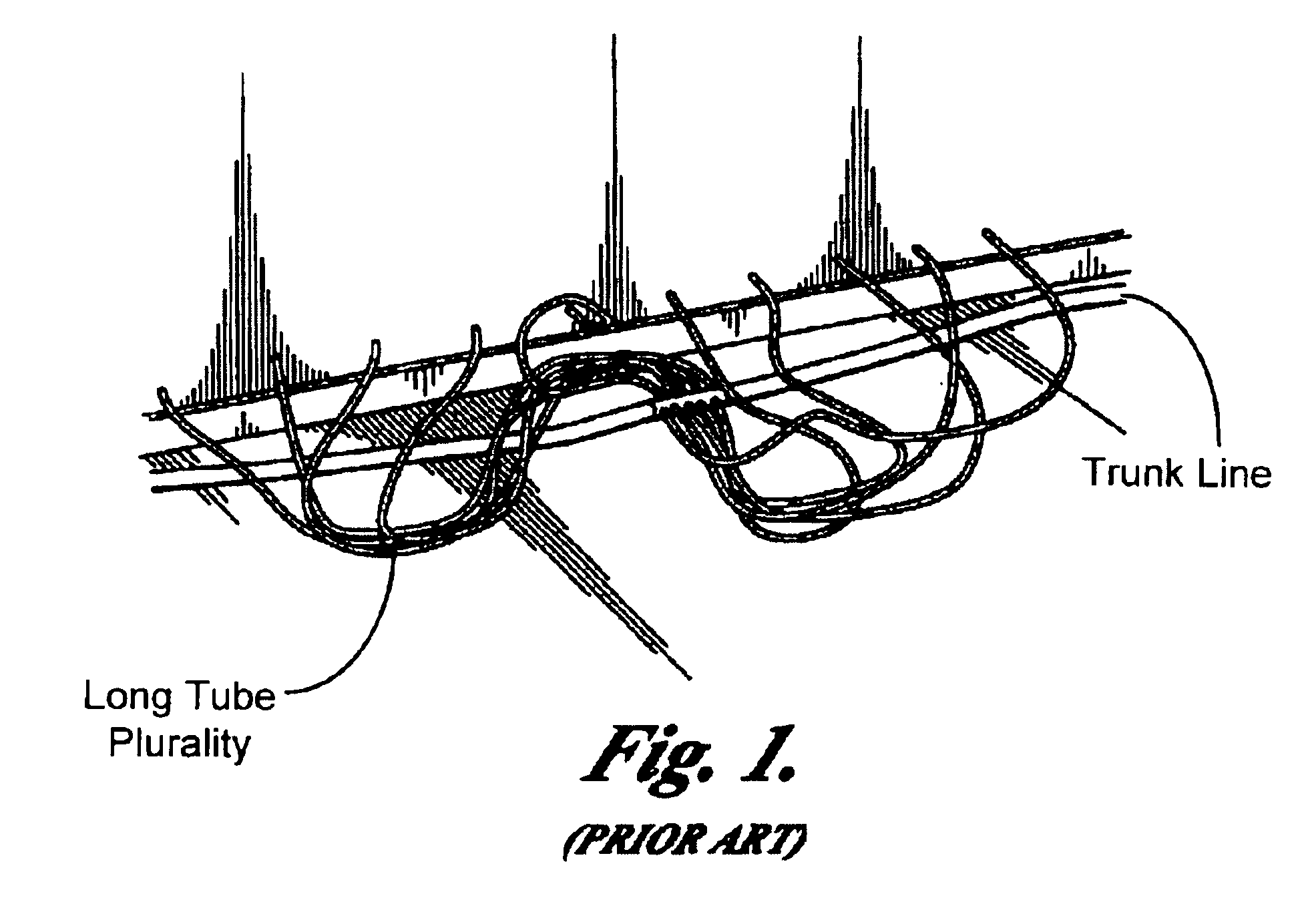
[0032]FIG. 1 is not an aspect of the present invention, but is useful in illustrating the configuration of my prior invention as set forth in U.S. patent application Ser. No. 08 / 890,141. It is also useful in understanding certain aspects and advantages of the active hoseline feature of present invention.

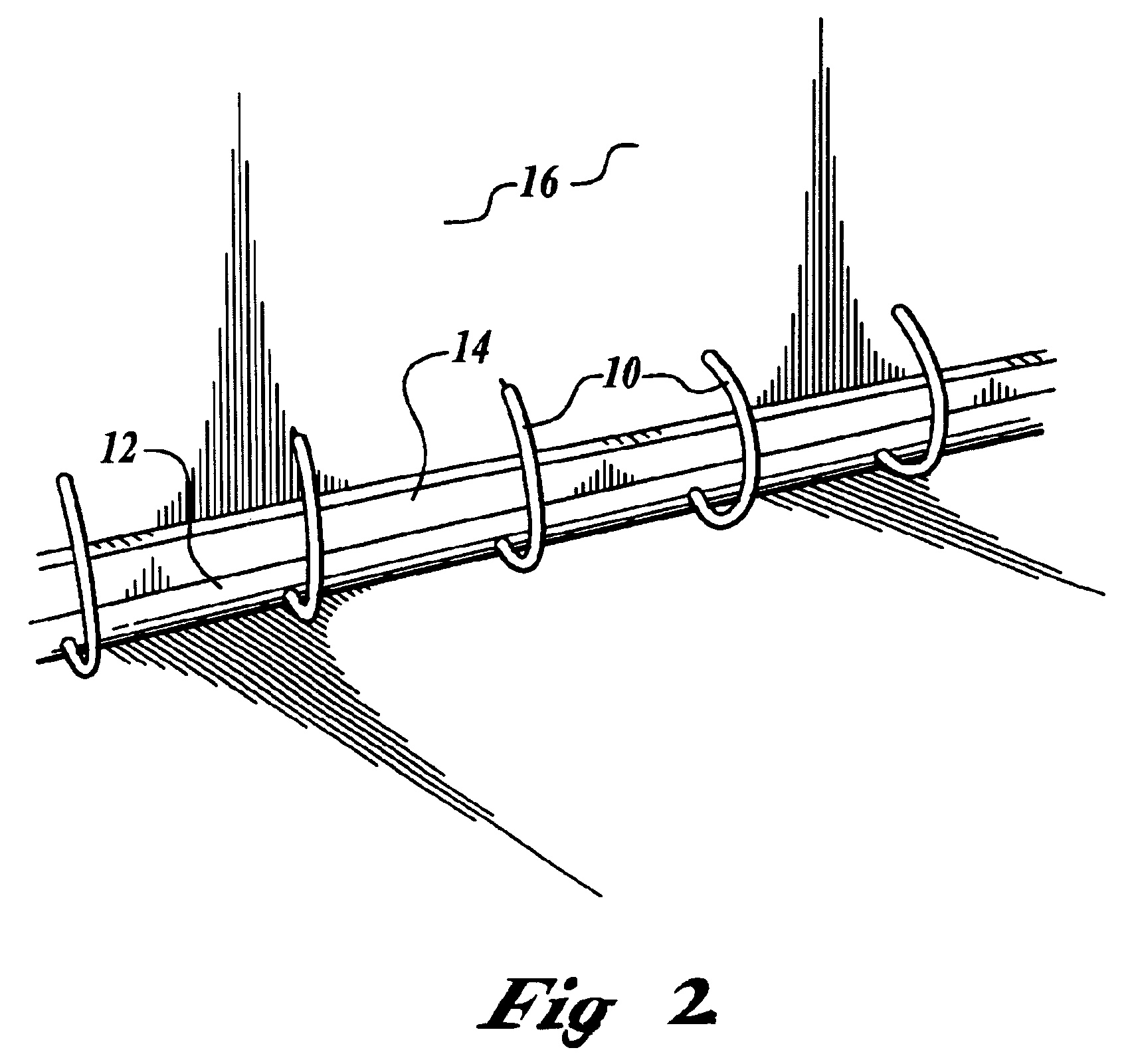
[0033]FIG. 2 does not show the details of the active hoseline feature of the present invention, but does illustrate the general configuration and context for the subsequent figures and description of the invention. It will be appreciated that while the tubes 10 of FIG. 2 are of uniform and short relatively short length, and uniform frequency along hose 12 for drying wall 16 just above baseboard 14, tubes 10 can be of any length, or of any frequency of distribution, regular or irregular, along hose 12. For example, in some applications it may be desirable for alternate tubes 10 to be long enough to reach a ceiling above the wall 16. In many applications, the preferred frequency of tub...


PUM


Abstract

The disclosed invention provides an improved method of drying wet or water damaged surfaces. The method uses a vacuum source, a manifold, and a plastic sheet covered grid. The grid includes a lattice formation with spaces to permit moisture and air to pass from and beneath the surface to the vacuum source.

Description

CROSS REFERENCE TO RELATED APPLICATIONS[0001]This application is a divisional of and claims priority to U.S. patent application Ser. No. 09 / 516,827 filed Mar. 1, 2000, now U.S. Pat. No. 6,647,639 and claims the benefit of U.S. provisional application Ser. No. 60 / 123,401 filed Mar. 8, 1999, each application is incorporated by reference in its entirety as if fully set forth herein.BACKGROUND OF INVENTION[0002]Unwanted water, introduced by flooding, precipitation or otherwise, causes millions, if not billions, of dollars of damage to structures every year. Generally, the amount of damage can be reduced, minimized, or even eliminated if the water can be removed from the structure shortly after its undesired entry into the structure. For example, if the water can be extracted promptly in some manner from the structure generally, and then from the cavities within walls, floors and other structural elements, then rot, mold, rust and other destructive effects of the unwanted water can be mi...

Claims


Application Information

Patent Timeline
IPC IPC(8): F26B23/10F26B21/00F26B23/00
CPCF26B21/00F26B23/10F26B21/004
Inventor STORRER, ERNEST J.
Owner INJECTIDRY SYST
Why Eureka
Try Eureka