Supercharge Your Innovation With Domain-Expert AI Agents!

Procedure for starting up a fuel cell system using a fuel purge

Inactive Publication Date: 2005-05-03
AUDI AG
View PDF14 Cites 45 Cited by
  • Summary
  • Abstract
  • Description
  • Claims
  • Application Information

AI Technical Summary

Benefits of technology

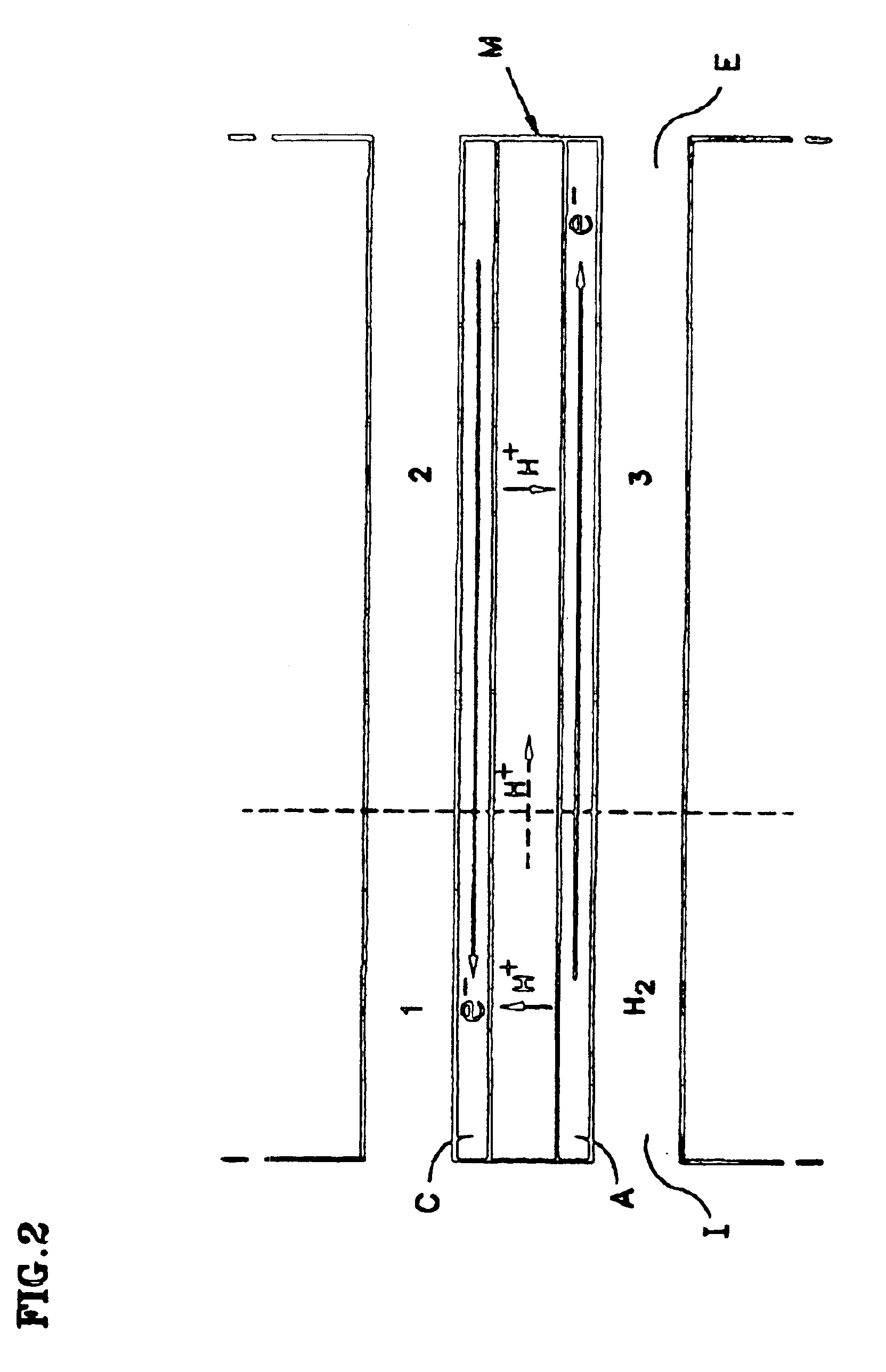
[0012]The flow of electrons from the portion of the anode that sees hydrogen to the portion of the anode that sees air results in a small change in the potential of the electron conductor. On the other hand, electrolytes in the membrane are relatively poor in-plane proton conductors, and the flow of protons results in a very significant drop in the electrolyte potential between zones H2 and 3.
[0014]One object of the present invention is to minimize any fuel cell catalyst and catalyst support corrosion occurring during start-up of the fuel cell, and to do it without using inert gas to purge air from the idle cells upon start-up.
[0015]In accordance with the present invention, fresh hydrogen containing fuel is used upon start-up to displace the air in the idle cell. The more rapidly the fresh hydrogen containing fuel is blown through the anode flow field upon start-up to displace the air therein, the quicker the hydrogen front (herein referred to as the hydrogen / air front since air is on one side of the front and hydrogen on the other) moves through the anode flow field, and the less time for the occurrence of corrosion of the platinum catalyst and catalyst support. (By “fresh” hydrogen containing fuel, it is meant fuel that has not yet been introduced into the fuel cell, as opposed to fuel that has been partially consumed within the cell and recirculated through the cell.) Although dependant upon the cell materials, desired length of cell life, and the number of shut-downs and start-ups likely to occur during that life, it is believed the hydrogen / air front will need to move through the anode in no more than about 1.0 second to satisfy performance needs over the life of a cell without requiring an inert gas purge. Preferably the hydrogen purge flow rate will move the hydrogen / air front (and thus all the air) through and out of the anode flow field in less than 0.2 seconds. For long life applications with frequent start-ups and shut-downs, such as automotive applications, a purge time of 0.05 seconds or less is most preferable.

Problems solved by technology

It was found that a cell stack assembly operated in this manner experienced rapid performance decay which had not previously been observed.
Further, it was discovered that a large number of start / stop cycles were more detrimental to cell performance than were a large number of normal operating hours under load.

Method used


Image

  • Procedure for starting up a fuel cell system using a fuel purge
  • Procedure for starting up a fuel cell system using a fuel purge
  • Procedure for starting up a fuel cell system using a fuel purge

Examples


Embodiment Construction

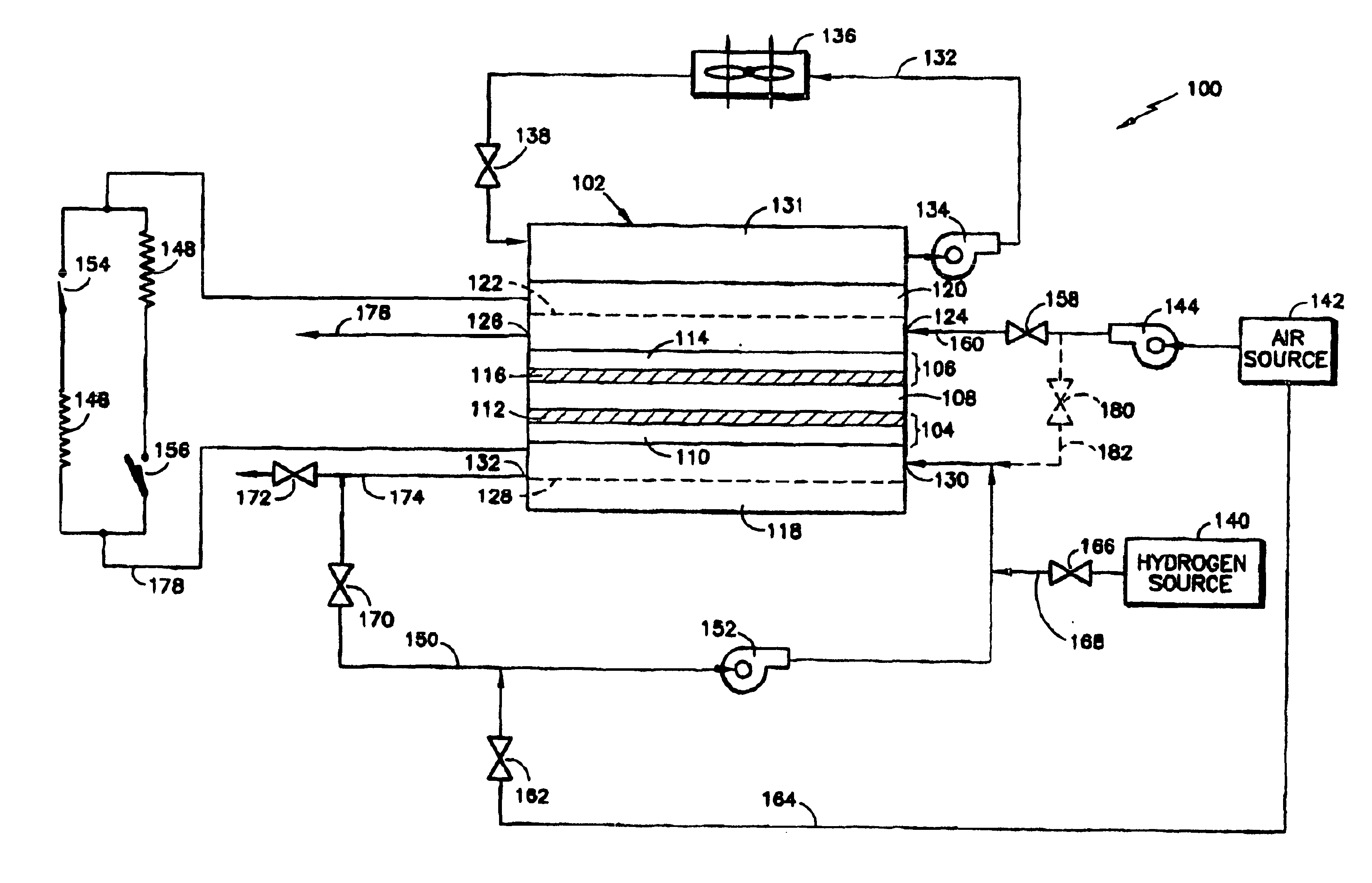
[0022]In FIG. 1, a fuel cell system 100 is shown. The system includes a fuel cell 102 comprising an anode 104, a cathode 106, and an electrolyte layer 108 disposed between the anode and cathode. The anode includes an anode substrate 110 having an anode catalyst layer 112 disposed thereon on the side of the substrate facing the electrolyte layer 108. The cathode includes a cathode substrate 114, having a cathode catalyst layer 116 disposed thereon on the side of the substrate facing the electrolyte layer 108. The cell also includes an anode flow field plate 118 adjacent the anode substrate 110, and a cathode flow field plate 120 adjacent the cathode substrate 114.

[0023]The cathode flow field plate 120 has a plurality of channels 122 extending thereacross adjacent the cathode substrate forming a cathode flow field for carrying an oxidant, preferably air, across the cathode from an inlet 124 to an outlet 126. The anode flow field plate 118 has a plurality of channels 128 extending ther...


PUM


Abstract

A procedure for starting up a fuel cell system that is disconnected from its primary load and has both its cathode and anode flow fields filled with air includes initiating a flow of air through the cathode flow field and rapidly displacing the air in the anode flow field by delivering a flow of fresh hydrogen containing fuel into the anode flow field, and thereafter connecting the primary load across the cell. Sufficiently fast purging of the anode flow field with hydrogen prior to connecting the cells to the load eliminates the need for purging the anode flow field with an inert gas, such as nitrogen, upon start-up.

Description

[0001]This application is a continuation-in-part of U.S. Ser. No. 09 / 742,481 filed on Dec. 20, 2000 now abandoned.BACKGROUND OF THE INVENTION[0002]1. Technical Field[0003]This invention relates to fuel cell systems and, more particularly, to procedures for starting up a fuel cell system.[0004]2. Background Information[0005]It is well known in the fuel cell art that, when the electrical circuit is opened and there is no longer a load across the cell, such as upon and during shut-down of the cell, the presence of air on the cathode, coupled with hydrogen fuel remaining on the anode, often cause unacceptable anode and cathode potentials, resulting in catalyst and catalyst support oxidation and corrosion and attendant cell performance degradation. It was thought that inert gas needed to be used to purge both the anode flow field and the cathode flow field immediately upon cell shut-down to passivate the anode and cathode so as to minimize or prevent such cell performance degradation. Fu...

Claims


Application Information

Patent Timeline
IPC IPC(8): H01M8/04
CPCH01M8/04223Y02E60/50H01M8/241H01M8/04303H01M8/04302H01M8/04228H01M8/04225H01M8/0267H01M8/2457H01M8/0258
Inventor REISER, CARL A.YANG, DELIANGSAWYER, RICHARD D.
Owner AUDI AG
Features
  • R&D
  • Intellectual Property
  • Life Sciences
  • Materials
  • Tech Scout
  • Unparalleled Data Quality
  • Higher Quality Content
  • 60% Fewer Hallucinations
Learn More