Method and apparatus for monitoring a photo-detector

a technology of photodetector and monitoring circuit, applied in the field of optical receivers, can solve the problems of extremely low power requirements of monitoring circuits above and beyond, and achieve the effect of low power requirements

Inactive Publication Date: 2005-05-03
II VI DELAWARE INC
View PDF9 Cites 34 Cited by
  • Summary
  • Abstract
  • Description
  • Claims
  • Application Information

AI Technical Summary

Problems solved by technology

The monitoring circuit also exhibits extremely low power requirements above and beyond those required to power the optical signal detector.

Method used


Image

  • Method and apparatus for monitoring a photo-detector
  • Method and apparatus for monitoring a photo-detector
  • Method and apparatus for monitoring a photo-detector

Examples


Embodiment Construction

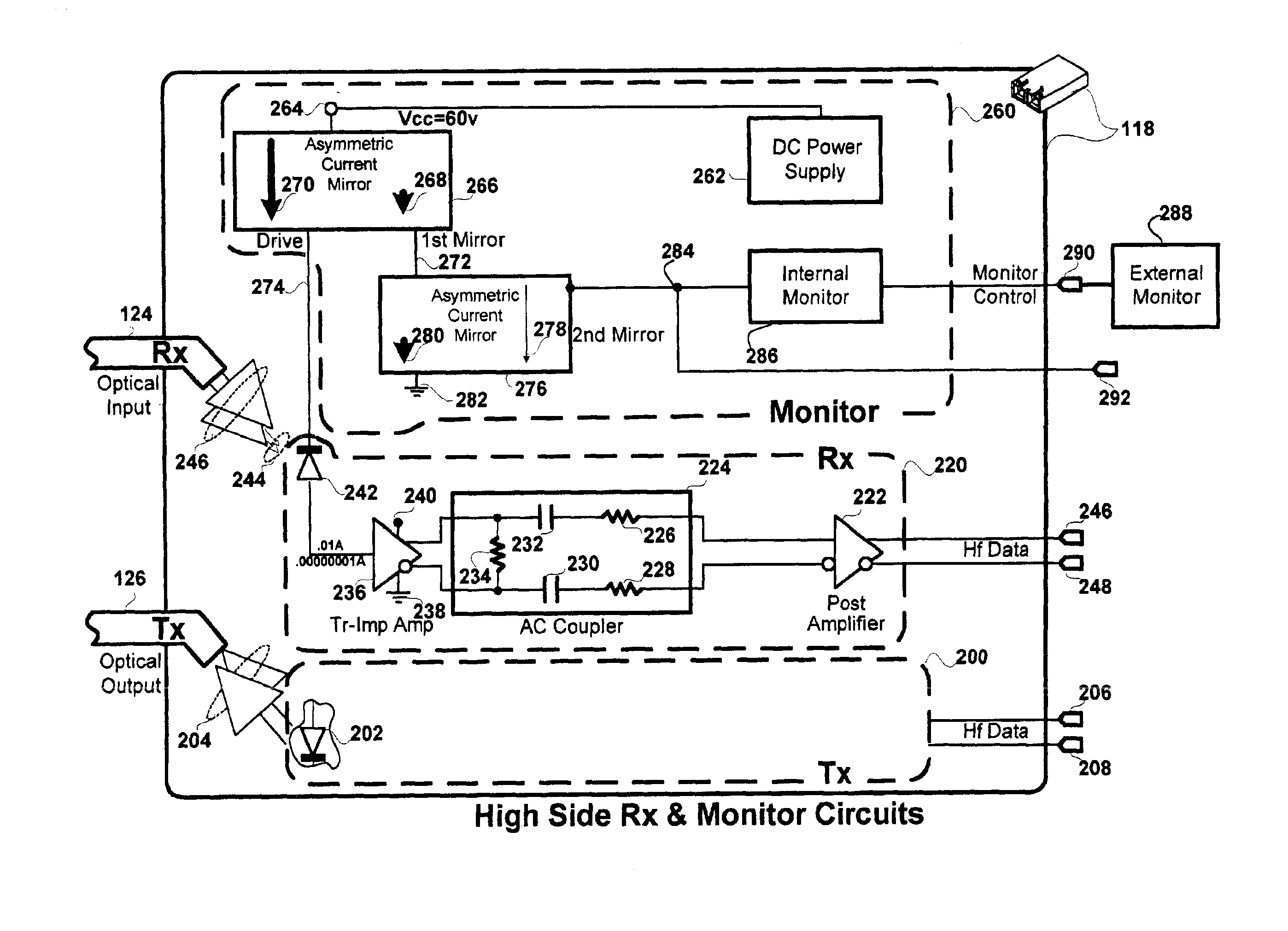
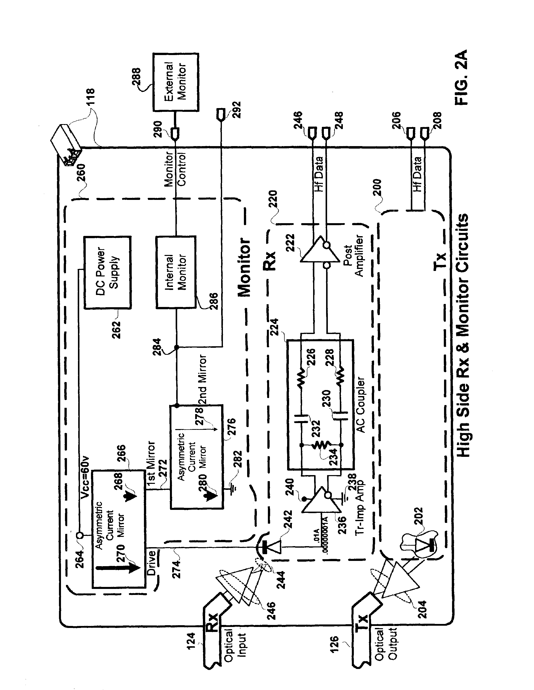
[0021]A method and apparatus is disclosed for monitoring an optical signal detector. The optical signal detector may be part of an optical receiver, transceiver or transducer. The monitoring of the photo-detector may be used to determine the strength of a received optical signal during setup or normal operation of an optical communication system. During normal operation received signal strength can be used to determine component aging. The monitor generates a mirror current which is highly compliant with the photo-detector current across a broad current range. The linearity of the monitor circuit makes it particularly suited for optical networks such as telecommunication networks with a broad range of lengths between network transceiver nodes. The monitoring circuit also exhibits extremely low power requirements above and beyond those required to power the optical signal detector.

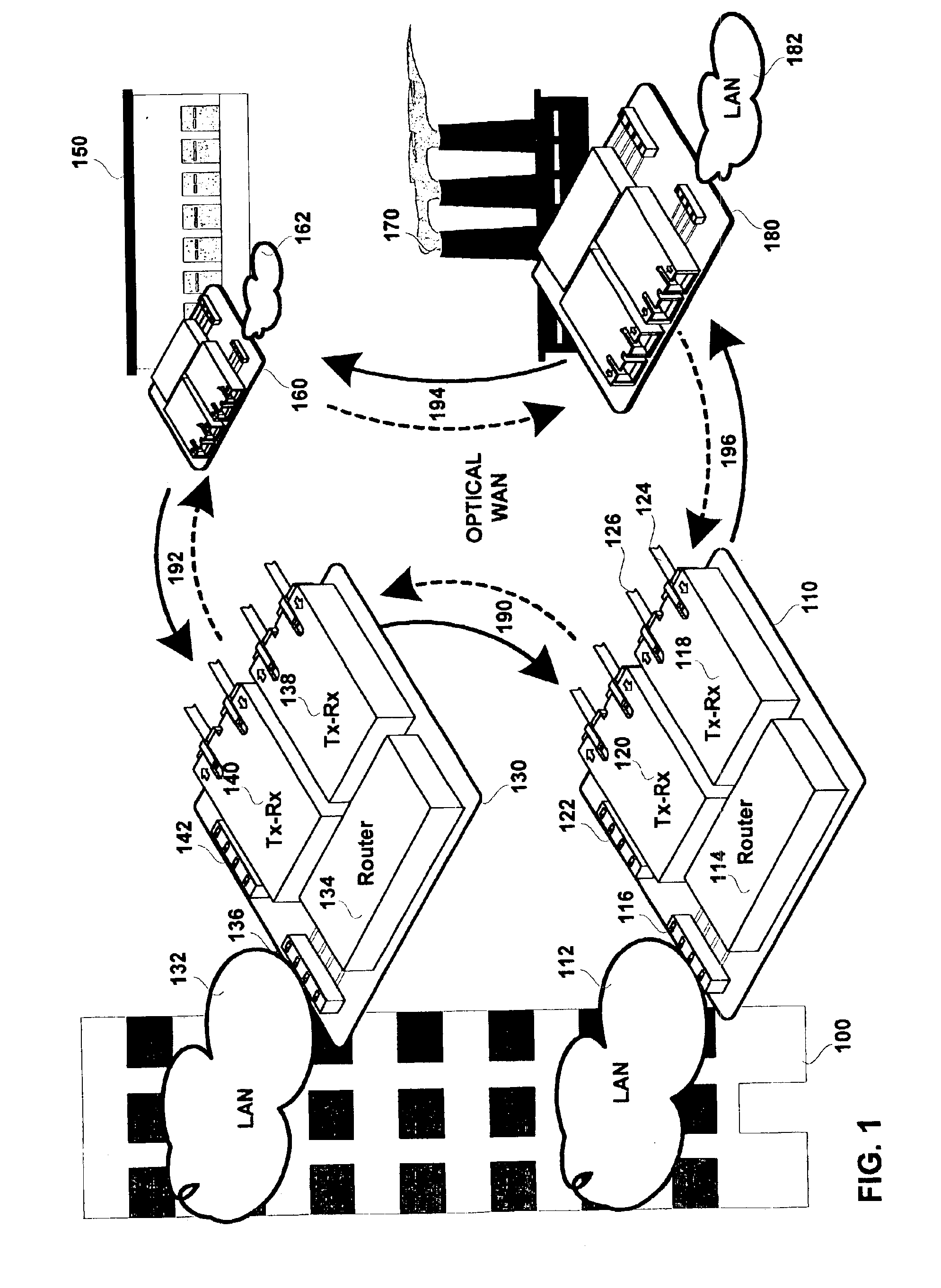
[0022]FIG. 1 shows a plurality of optical transceivers coupled to one another to form a wide area optica...


PUM


Abstract

An optical signal detector monitoring circuit can include a current divider current mirror (CDCM) and a current multiplier current mirror (CMCM). A mirror leg of the CDCM generates a current corresponding with a part of the CDCM's primary leg current. The CMCM's primary leg couples to the CDCM's mirror leg. The CMCM generates a mirror leg current corresponding with a multiple of its primary leg current. Another circuit can include a first current mirror having a primary current leg (PCL), coupled between an optical signal detector and one of an electrical source and an electrical sink, that exhibits a resistance corresponding with a part of the resistance of the first current mirror's mirror current leg (MCL). The circuit's second current mirror has a MCL that exhibits a resistance corresnonding with a part of the resistance of the second current mirror's PCL, which couples with the first current mirror's MCL.

Description

BACKGROUND OF THE INVENTION[0001]1. Field of Invention[0002]The field of the present invention relates in general to optical networks and more particularly to optical receivers.[0003]2. Description of the Related Art[0004]In communication systems light beams are increasingly used for transmitting information. The demand for communication bandwidth has resulted in a conversion of long and short haul communication trunk lines from copper to fiber optic (digital) communication. The wide spectral characteristics of fiber optics support broadband signals at very high data rates, gigabits per second.[0005]Generally, an optical source, i.e. transmitter, converts an electrical signal, either digital or analog, to a modulated light beam which is then passed through an optical fiber to an optical detector, i.e. receiver, that extracts an electrical signal from the received light beam. A fiber may be shared with different communication channels using frequency, time or other forms of multiplex...

Claims


Application Information

Patent Timeline
Patent Type & Authority Patents(United States)
IPC IPC(8): H01J40/00H01J40/14G02B
CPCH04B10/0799H01L31/02016
Inventor DOUMA, DARIN JAMESBURDICK, STEPHAN C.
Owner II VI DELAWARE INC
Why Eureka
Try Eureka