Device for operating a high pressure discharge lamp

a high-pressure discharge and lamp technology, applied in the direction of instruments, basic electric elements, light sources, etc., can solve the problem of not being able to quickly discharg

Inactive Publication Date: 2005-05-03
USHIO DENKI KK
View PDF8 Cites 16 Cited by
  • Summary
  • Abstract
  • Description
  • Claims
  • Application Information

AI Technical Summary

Benefits of technology

[0023]In such a situation, the lamp can be started in a short time when the high voltage pulse is operated only at a certain polarity of the AC voltage, as was described above, i.e., only when the polarity of the AC voltage during starting of the electrode, with a large amount of adhering mercury, is negative is the high voltage pulse for starting produced. In this way, the lamp can be started without a glow discharge forming.

Problems solved by technology

However, in the reverse case, the transition to the arc discharge does not take place quickly.

Method used


Image

  • Device for operating a high pressure discharge lamp
  • Device for operating a high pressure discharge lamp
  • Device for operating a high pressure discharge lamp

Examples


Embodiment Construction

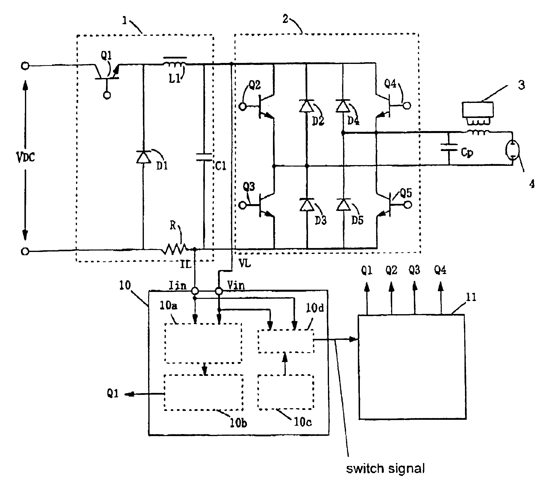
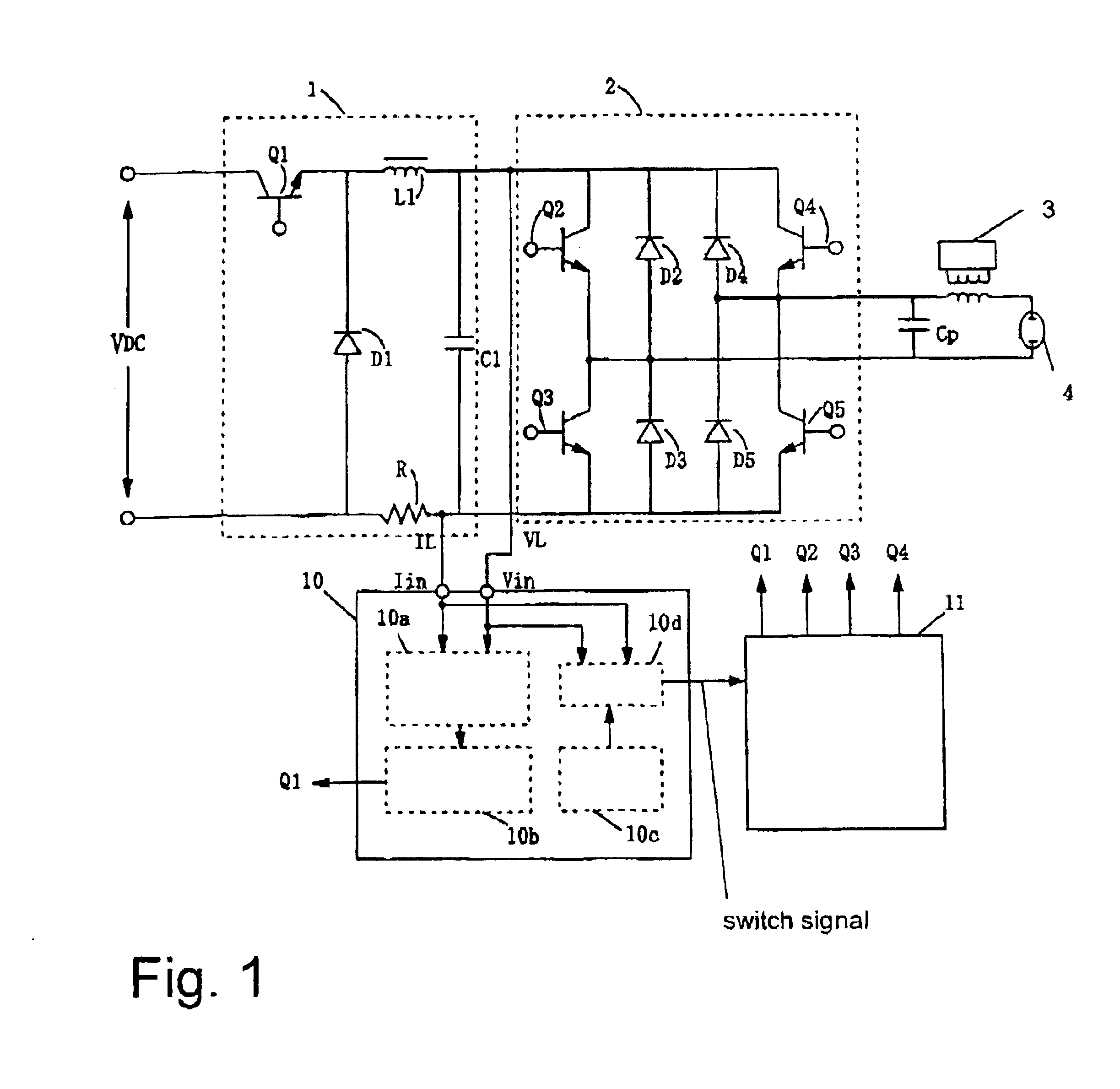
[0031]FIG. 1 is a schematic of one embodiment of a device of the invention for operating a high pressure discharge lamp. FIG. 1 shows the arrangement of a lighting circuit using a full bridge circuit. However, a half bridge circuit or a push-pull circuit can also be used.

[0032]As is shown in FIG. 1, the circuit in this embodiment is connected to a voltage reduction chopper circuit 1 which is supplied with a DC voltage, and also to the output side of the voltage reduction chopper circuit 1; it comprises a full bridge circuit 2 which converts the DC voltage into a voltage with rectangular waves, and of an igniter device 3 which when the lamp is started produces a high voltage pulse. An AC voltage with rectangular waves or a DC voltage which is output by the full bridge circuit 2 is applied to the discharge lamp 4. A bypass capacitor Cp is connected parallel to the output side of the full bridge circuit 2 and bridges the high voltage pulse which is produced by the igniter device 3.

[003...


PUM


Abstract

A device which improves the starting of a high pressure discharge lamp containing a large amount of mercury, in which the amount of mercury adhering to the lamp electrodes is not the same, by shortening the formation time of the glow discharge in order to reduce the sputtering of the electrodes to a minimum. When the discharge lamp starts, an AC voltage with rectangular waves produced by the full bridge circuit is applied to the discharge lamp. Next, a high voltage pulse is superimposed and applied by an igniter device; the pulse is synchronized to the polarity of the above described AC voltage with rectangular waves. As a result, an alternating current discharge is started in the discharge lamp. Then, the ON/OFF state of the switching devices in the full bridge circuit is fixed and a direct current voltage is applied to the lamp. After a pre-selected time has expired after the transition into direct current operation, the full bridge circuit is operated such that rectangular alternating current waves form. The AC voltage with rectangular waves is then applied to the discharge lamp and a transition into steady-state operation is carried out.

Description

BACKGROUND OF THE INVENTION[0001]1. Field of the Invention[0002]The invention relates to a device for operating a high pressure discharge lamp. The invention relates especially to a device for operating a high pressure discharge lamp which is suited for use for a light source of a projector of the projection type or the like.[0003]2. Description of the Related Art[0004]In a device for operating a discharge lamp, it is known to employ a circuit having a full bridge system of a low frequency of 50 / 60 Hz in which a high frequency of roughly 20 kHz is superimposed and operation with an alternating high frequency achieved (for example, Japanese patent disclosure HEI 6-65175).[0005]The process of starting the known discharge lamp is as follows. Beginning in the no-load state an igniter circuit superimposes a high voltage pulse which starts a discharge lamp. Thereafter, from the current supply of the feed device of the discharge space the lamp passes from a glow discharge state into an arc...

Claims


Application Information

Patent Timeline
Patent Type & Authority Patents(United States)
IPC IPC(8): H05B41/38H05B41/28H05B41/288H05B41/18H05B41/24
CPCH05B41/288H05B41/38Y10S315/05Y10S315/07
Inventor ARIMOTO, TOMOYOSHISUZUKI, YOSHIKAZU
Owner USHIO DENKI KK
Why Eureka
Try Eureka