Characteristics adjustment method of image forming apparatus, manufacturing method of image forming apparatus and characteristics adjustment apparatus of image forming apparatus

a manufacturing method and image forming technology, applied in the field of characteristics adjustment manufacturing method characteristics adjustment apparatus of image forming apparatus, can solve the problems of difficult to illustrate the characteristics of respective electron sources in an identical scale, the fluctuation of characteristics of respective electron sources appears as luminance fluctuation, and the emission current is extremely small. , to achieve the effect of simple process

Inactive Publication Date: 2005-05-03
CANON KK
View PDF14 Cites 25 Cited by
  • Summary
  • Abstract
  • Description
  • Claims
  • Application Information

AI Technical Summary

Benefits of technology

[0045]The present invention has been devised in view of the above and other drawbacks, and it is an object of the present invention to provide a characteristic adjustment method for an image forming apparatus, a manufacturing method for an image forming a

Problems solved by technology

Further, the emission current Ie is extremely small compared with the device current If and it is difficult to illustrate them in an identical scale.
However, since there are a large number of electron sources unlike a CRT or the like, if an image forming apparatus is manufactured using this, there is a problem in that fluctuation of characteristics of respective electron sources appears as fluctuation of luminance.
However, a highly advanced manufacturing facility and an extremely strict process management are required if it is attempted to remove all of these

Method used


Image

  • Characteristics adjustment method of image forming apparatus, manufacturing method of image forming apparatus and characteristics adjustment apparatus of image forming apparatus
  • Characteristics adjustment method of image forming apparatus, manufacturing method of image forming apparatus and characteristics adjustment apparatus of image forming apparatus
  • Characteristics adjustment method of image forming apparatus, manufacturing method of image forming apparatus and characteristics adjustment apparatus of image forming apparatus

Examples


first embodiment

(First Embodiment of the Characteristic Adjustment Method for an Image Forming Apparatus)

[0101]A first embodiment of a characteristic adjustment method for an image forming apparatus in accordance with the present invention will be hereinafter described. In the embodiment described below, an example in which the present invention is applied to an image forming apparatus using a multi-electron beam source is shown.

[0102]First, a structure and a manufacturing method of a display panel of the image forming apparatus to which the present invention is applied will be described.

(A Structure and a Manufacturing Method of a Display Panel)

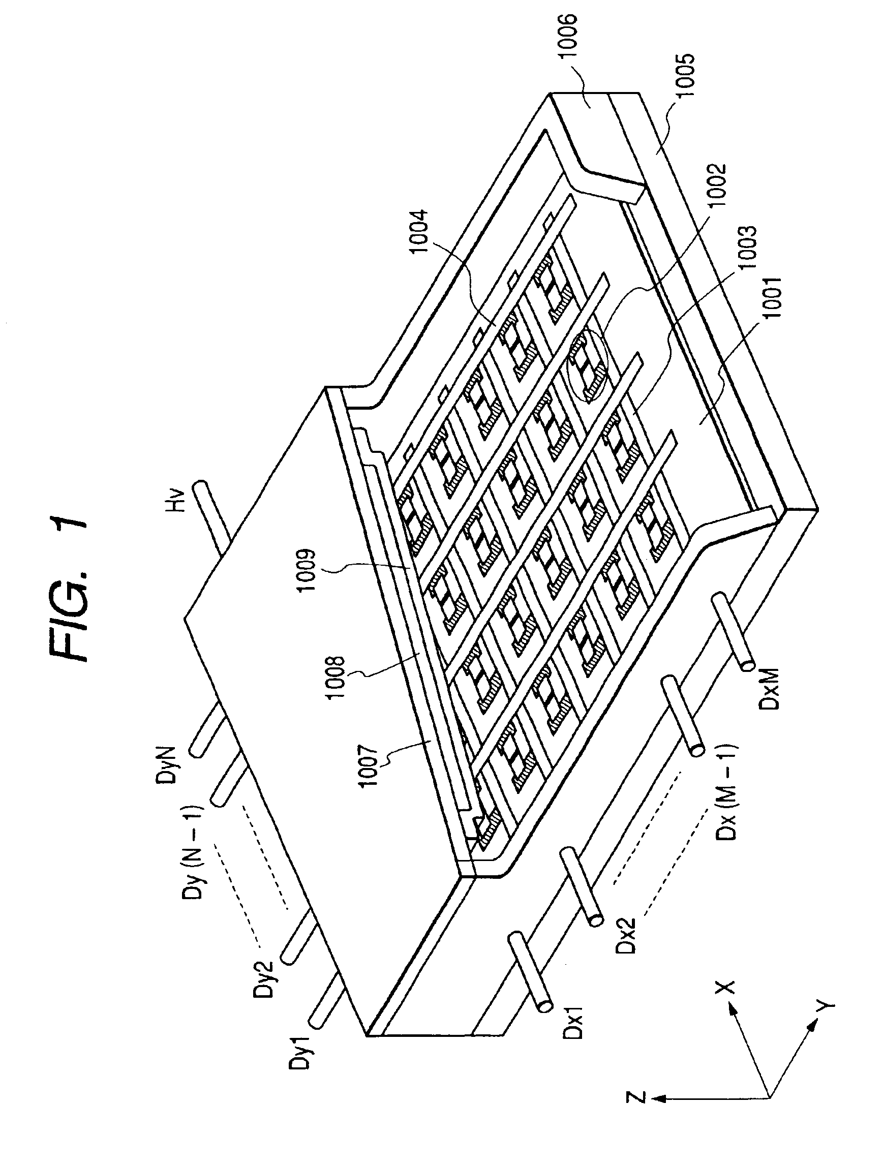
[0103]FIG. 1 is a perspective view of a display panel of the image forming apparatus to which the present invention is applied, in which a part of the panel is cut away in order to show its internal structure.

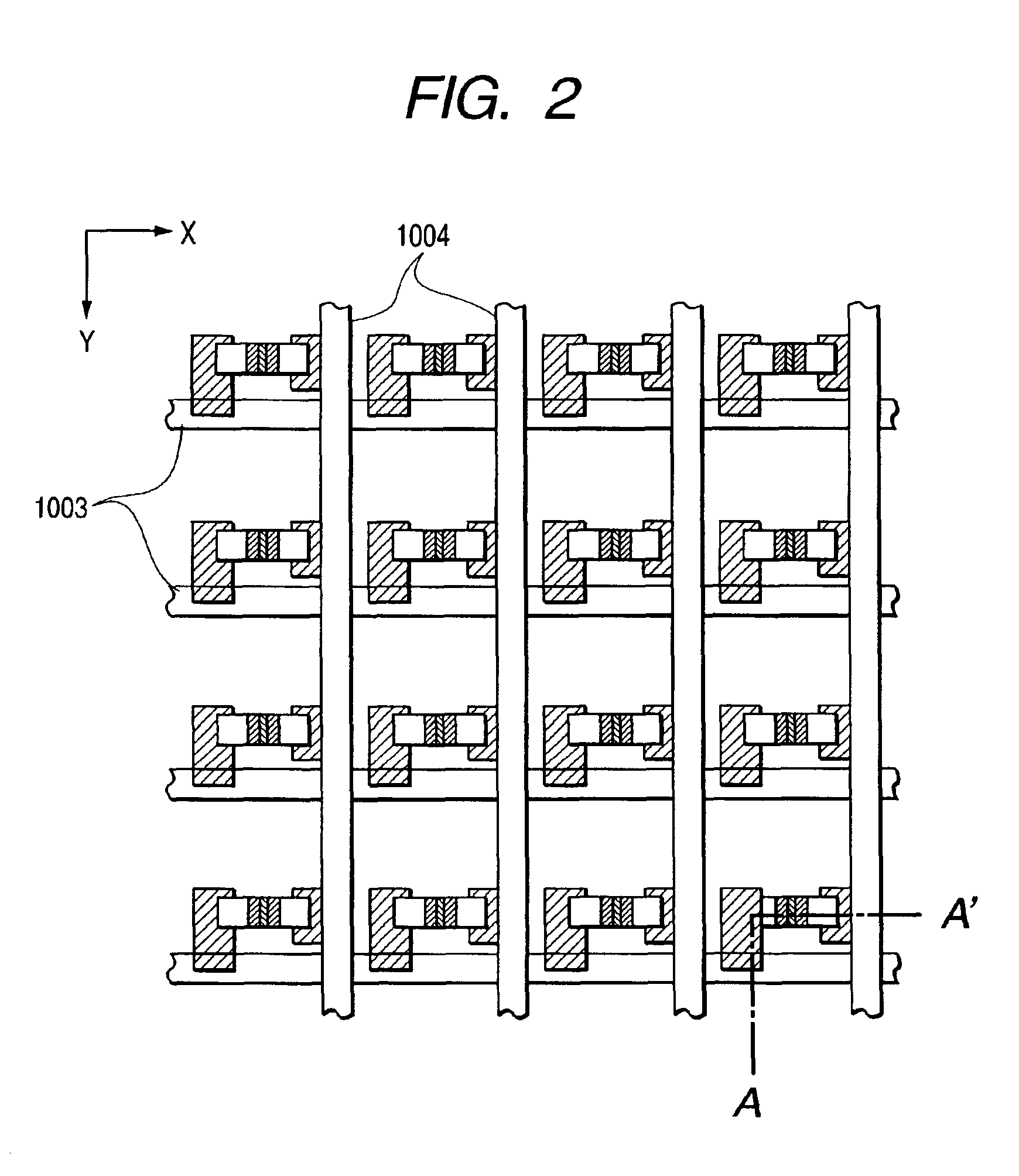
[0104]In the figure, reference numeral 1005 denotes a rear plate; 1006, a sidewall; and 1007, a face plate. An airtight container for maintaining the ...

second embodiment

(Second Embodiment of the Characteristic Adjustment Method for an Image Forming Apparatus)

[0210]Next, a second embodiment of the characteristic adjustment method for an image forming apparatus in accordance with the present invention will be described.

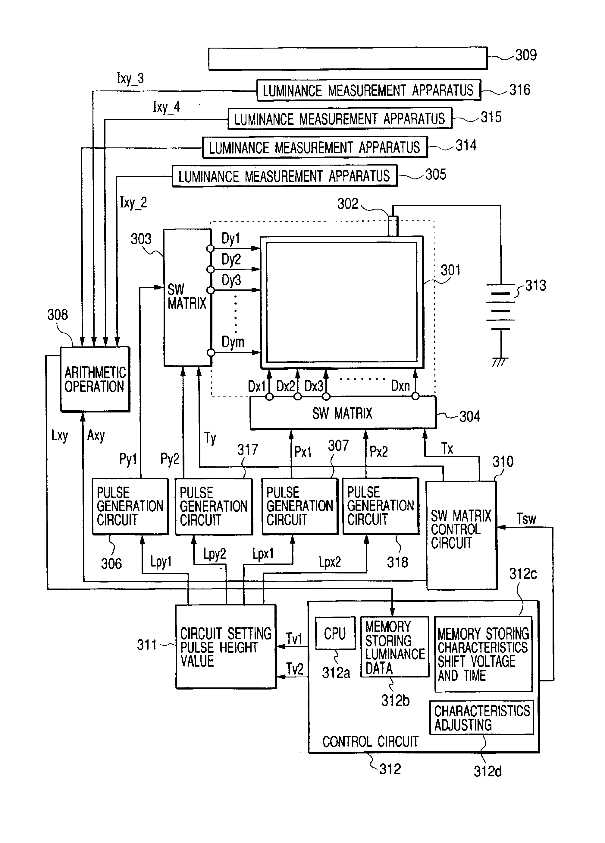
[0211]FIG. 12 shows a structure of an apparatus for arranging an electron emitting characteristic of each surface conduction electron emission device of the display panel 301 along a certain target set value. Luminance measurement systems 314, 315 and 316 and pulse generation circuits 317 and 318 are added to the structure shown in FIG. 4. FIG. 12 is a schematic diagram of an image forming apparatus using a multi-electron source and a characteristic adjustment apparatus for an image forming apparatus for applying a characteristic adjustment signal to this image forming apparatus, which are used in the second embodiment of the characteristic adjustment method for an image forming apparatus in accordance with the present invention.

[0212]...


PUM


Abstract

There is provided a characteristic adjustment method for an image forming apparatus that is provided with a multi-electron source in which a plurality of electron-emitting devices are electrically connected by wiring and arranged on a substrate and a fluorescent member for emitting light by irradiation of an electron beam, the method including: a measurement step of dividing a display portion of the image forming apparatus into a plurality of areas and measuring light emitting characteristics of at least one or more of the electron-emitting devices in the respective divided areas, and a shifting step of shifting the light emitting characteristics of the electron-emitting devices in the divided areas to individual characteristic target values by applying a characteristic shift voltage to the electron-emitting devices.

Description

BACKGROUND OF THE INVENTION[0001]1. Field of the Invention[0002]The present invention relates to an image forming apparatus provided with a large number of surface conduction electron emission devices and to a characteristics adjustment method for an image forming apparatus, a manufacturing method for an image forming apparatus and a characteristics adjustment apparatus that are preferably applied to such an image forming apparatus.[0003]2. Related Background Art[0004]Up to now, there have been known two types of electron-emitting devices, namely, a hot cathode device and a cold cathode device. As the cold cathode device, for example, a field emission device, a metal / insulator / metal electron-emitting device and a surface conduction electron emission device are known.[0005]Among the electron-emitting devices known as the cold cathode device, the surface conduction electron emission device (hereinafter also referred to simply as device) utilizes a phenomenon that electron emission is ...

Claims


Application Information

Patent Timeline
IPC IPC(8): G09G3/00G09G3/22H01J31/12H01J9/44H01J9/02H01J9/42
CPCG09G3/006H01J31/127G09G3/22G09G2320/0285H01J9/44
Inventor YAMANO, AKIHIKOKUNO, MITSUTOSHIAOKI, SHUJIOGUCHI, TAKAHIRO
Owner CANON KK
Why Eureka
Try Eureka