Color measurement instrument with modulated illumination

a color measurement and modulation technology, applied in instruments, spectrometry/spectrophotometry/monochromators, optical radiation measurement, etc., can solve the problems of unsatisfactory application cannot relax the requirement of environmental robustness, simplicity and reliability, etc., to achieve effective modulation, effective illumination, and simple

Inactive Publication Date: 2005-05-03
X-RITE
View PDF7 Cites 51 Cited by
  • Summary
  • Abstract
  • Description
  • Claims
  • Application Information

AI Technical Summary

Benefits of technology

[0010]The aforementioned problems are overcome in the present invention in which a color measurement instrument uses a continuously modulated illuminator so that the detector can be tuned to the modulated reflected light and can ignore the unmodulated ambient light. The instrument modulates the illuminator (one or more outputs) at a specific carrier frequency and then uses narrow band filtering in the detector to see only light that is modulated at the specific frequency. Consequently, the instrument nullifies the effects of ambient light in a fashion that is relatively simple, efficient, and inexpensive.
[0011]In the preferred embodiment, the illuminator is one or more light-emitting diodes (LEDs), which are becoming increasingly effectively used for illumination. The light output of LEDs can be effectively modulated in ways that other light sources cannot. Using continuously modulated LED illumination is an innovative enhancement to the RGB LED illumination of the above noted prior art because it uses a single wide band sensor and relies on the pseudo-monochromatic nature of LED light to provide the needed spectral color differentiation. Additionally, the present invention may use more than the three RGB colors of the prior art. Though slightly more complex in design, the present invention provides several distinct advantages. Differentiation of the color signal from the color noise of ambient light is done almost entirely in a simple frequency domain rather than having to rely on spatial means (i.e. optical geometries) or time differential means (i.e. measurement of ambient with signal minus measurement of ambient without signal) to achieve g

Problems solved by technology

Consequently such instrumentation is somewhat expensive.
Such sensors usually differentiate color no finer than what could very easily be discerned by human vision in less than ideal lighting.
Yet these applications cannot relax their requirement for environmental robustness, simplicity and reliability as demanded by industrial ap

Method used


Image

  • Color measurement instrument with modulated illumination
  • Color measurement instrument with modulated illumination
  • Color measurement instrument with modulated illumination

Examples


experiment 1

II. Experiment 1

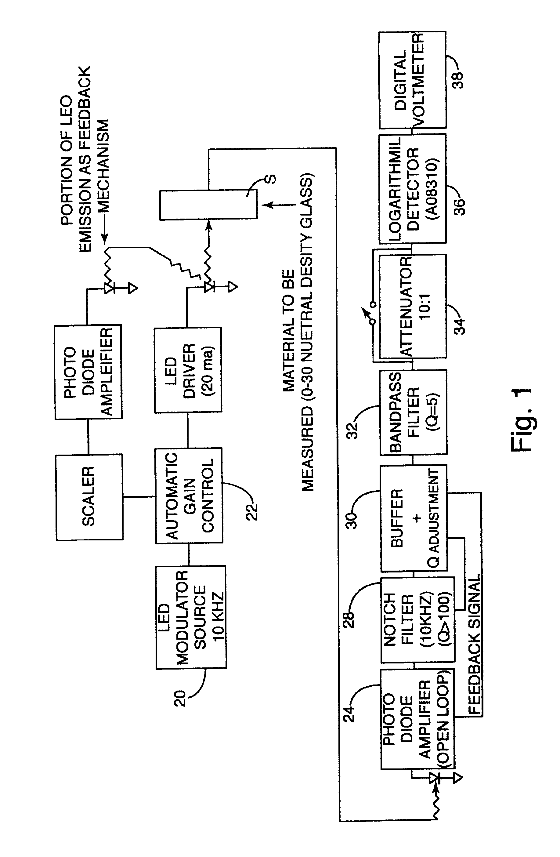
[0025]In Experiment 1, circuitry was developed to demonstrate the advantages of using a current modulated LED as a light source and combining that light source with frequency selective detection / amplification. The goal was to verify that modulated LED light could be measured in ambient light conditions with a dynamic range of three to four decades. FIG. 1 shows a block diagram of Experiment 1. The LED light source was a 520 nanometer (nm) green LED, which was chosen because its peak wavelength was close to the peak sensitivity of the human eye and because green LEDs represent the middle of the road in terms of LED efficiency (reds are more efficient while blues are less efficient). The LED was current modulated by making it, with a current limiting resistor, the load in a voltage controlled current sink (VCCS). The LED was operated at a nominal 20 milli-amperes DC, which is the ideal operation point for most LEDs in a 5 mm. package. A 10 kHz sine wave modulator 20 wa...

experiment 2

IV. Experiment 2

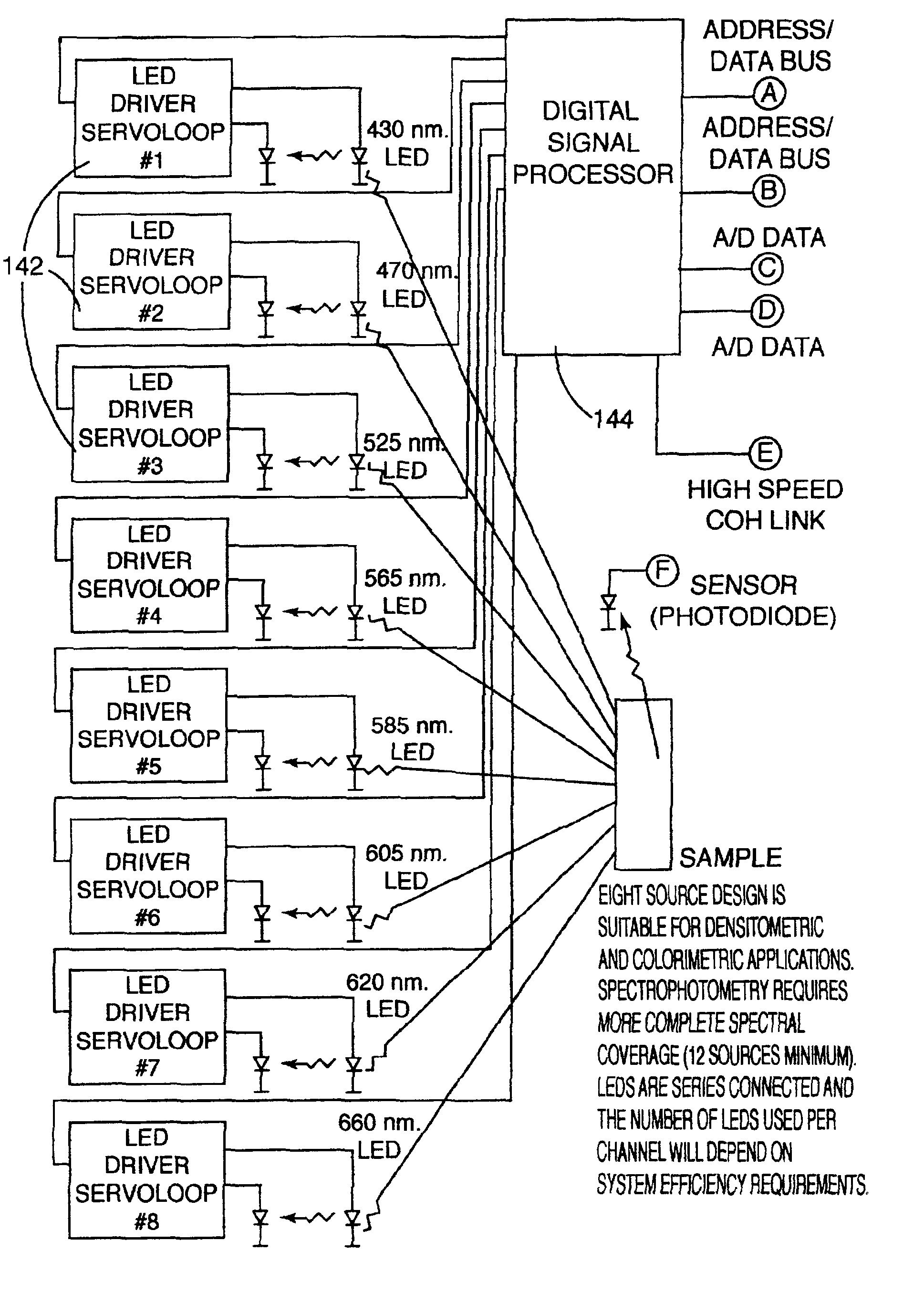
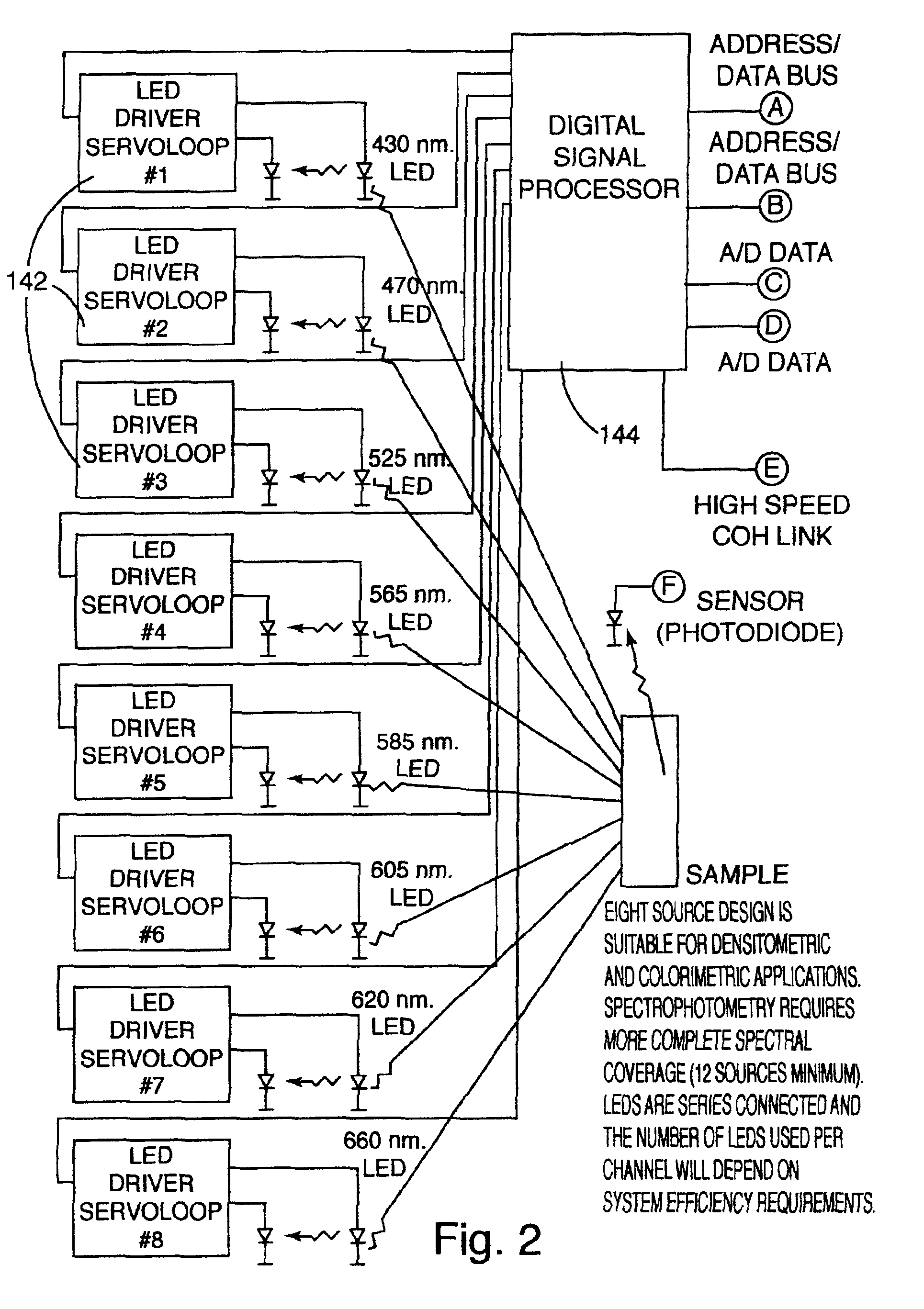
[0048]Experiment 2 tested the various components of a MLSA design. FIG. 4 shows a block diagram of Experiment 2. The first step was to design an LED servo that is simple, stable, and accurate at 100 KHz and a high speed photodiode detector / amplifier circuit. FIG. 5 shows a schematic of experimental circuits. Designing the detector / amplifier circuitry was challenging because of the effect of photodiode capacitance, which must be minimized if frequency response is to be maximized. The best or most cost-effective solution appeared to be a combination of a number of techniques such as reverse biasing the photodiode to reduce photodiode capacitance, bootstrapping the photodiode to reduce the effect of photodiode capacitance, selecting an optimal operational amplifier with reduced capacitance at the amplifier inputs, and incorporating a cascode (common base transistor) amplifier between the photodiode and trans-impedance amplifier to swamp out the photodiode capacitance. C...


PUM


Abstract

An instrument and method for measuring light or color using modulated illumination. The system includes an LED illuminator modulated at a specific frequency for illuminating the sample, and a sensor capable of differentiating between the modulated light from the sample and unmodulated ambient light. The instrument is therefore capable of “seeing” only light from the sample, while ignoring ambient light. In a second embodiment, the system includes multiple illuminators of different colors each modulated at a unique frequency so that the sample can be measured at multiple at each of the different frequencies.

Description

PRIORITY CLAIM[0001]This application claims the benefit of U.S. Provisional Application No. 60 / 291,534 filed May 16, 2001 entitled “Modulating LEDs to Maintain Selectivity and Sensitivity in Density or Color Measuring Instrumentation” and U.S. Provisional Application No. 60 / 351,164 filed Jan. 23, 2002 entitled “Light or Color Measuring Instrumentation Based on Modulated LED Illumination.”BACKGROUND OF THE INVENTION[0002]1. Field of the Invention[0003]The present invention relates to color measurement instruments and, more specifically, to such instruments using light-emitting diodes (LEDs) as the illumination source.[0004]2. Description of the Art[0005]The ability to monitor and / or control color is beneficial in many areas of manufacturing. The performance requirements for measuring color from application to application differ greatly and the hardware solutions that result are perhaps as varied as the applications they serve. Nonetheless, a simple model can be posed where color meas...

Claims


Application Information

Patent Timeline
IPC IPC(8): G01N21/25G01J3/00G01J3/50G01J3/10G01J3/42G01J1/42G01J3/433
CPCG01J3/10G01J3/50G01J3/501G01N21/255G01J3/524G01J3/433G01N2201/0691G01J2001/4242G01N2201/0625G01N2201/0627
Inventor VANDER JAGT, PETER G.PETERSON, STEVEN H.
Owner X-RITE
Why Eureka
Try Eureka