Printer-built-in image-sensing apparatus and electric-consumption control method thereof

a technology of which is applied in the field of printing-built-in image-sensing apparatus and electric consumption control method thereof, can solve the problems of inability to perform extra printing, inability to provide excellent printout, and inability to obtain copied image(s) to be further degraded in image quality, so as to prevent poor printout

Inactive Publication Date: 2005-05-03
CANON KK
View PDF9 Cites 102 Cited by
  • Summary
  • Abstract
  • Description
  • Claims
  • Application Information

AI Technical Summary

Benefits of technology

[0018]The present invention has been made in consideration of the above situation, and has its object to provide a printer-built-in image-sensing apparatus which ...

Problems solved by technology

However, the conventional instant cameras which record sensed images on instant films cannot provide as excellent printouts as still cameras which use silver chloride films in the point of image quality and preservation.
Further, when a plurality of printouts are required from the same sensed image, instant cameras cannot perform extra printing.
Therefore in such a case, the single printout must be copied, and the obtained copied image(s) is in further degraded image quality.
If undesirable images from failed image sensing or unnecessary images are included in the sensed images, the instant film is wasted.
Furthermore, as it is impossible to print only necessary images later, it is inconvenient for users.
This requires a very large amount of electricity for printing.
However, as this printer performs printing by repeating print operation of a predetermined width in a print-sheet feeding direction, it takes a long time to print.
However, in all of these printers, energy is applied to the print head for printing on a print sheet.
Therefore the power source must maintain ...

Method used


Image

  • Printer-built-in image-sensing apparatus and electric-consumption control method thereof
  • Printer-built-in image-sensing apparatus and electric-consumption control method thereof
  • Printer-built-in image-sensing apparatus and electric-consumption control method thereof

Examples


first embodiment

[First Embodiment]

[0041]A first embodiment of the present invention will be described with reference to FIGS. 1 to 5.

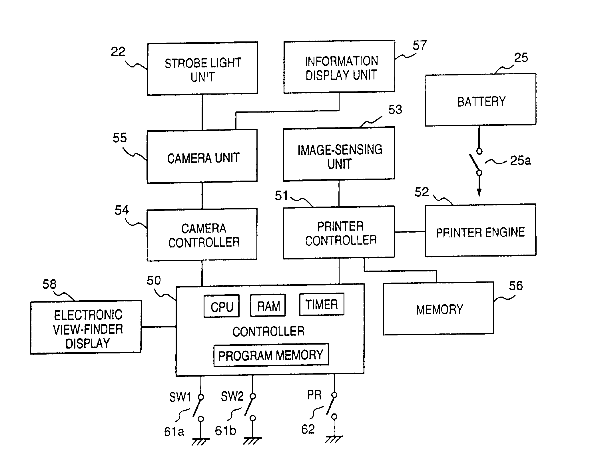
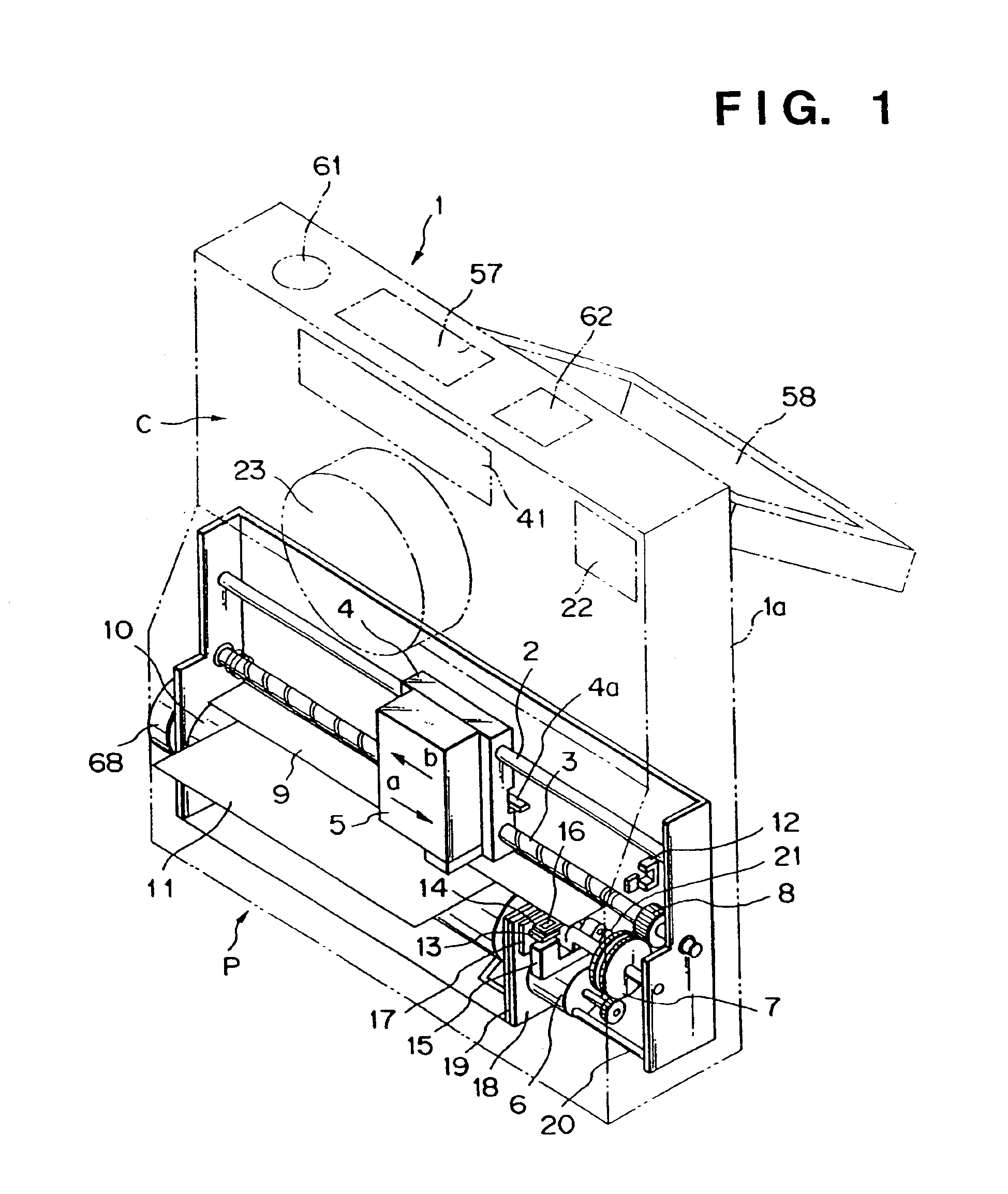
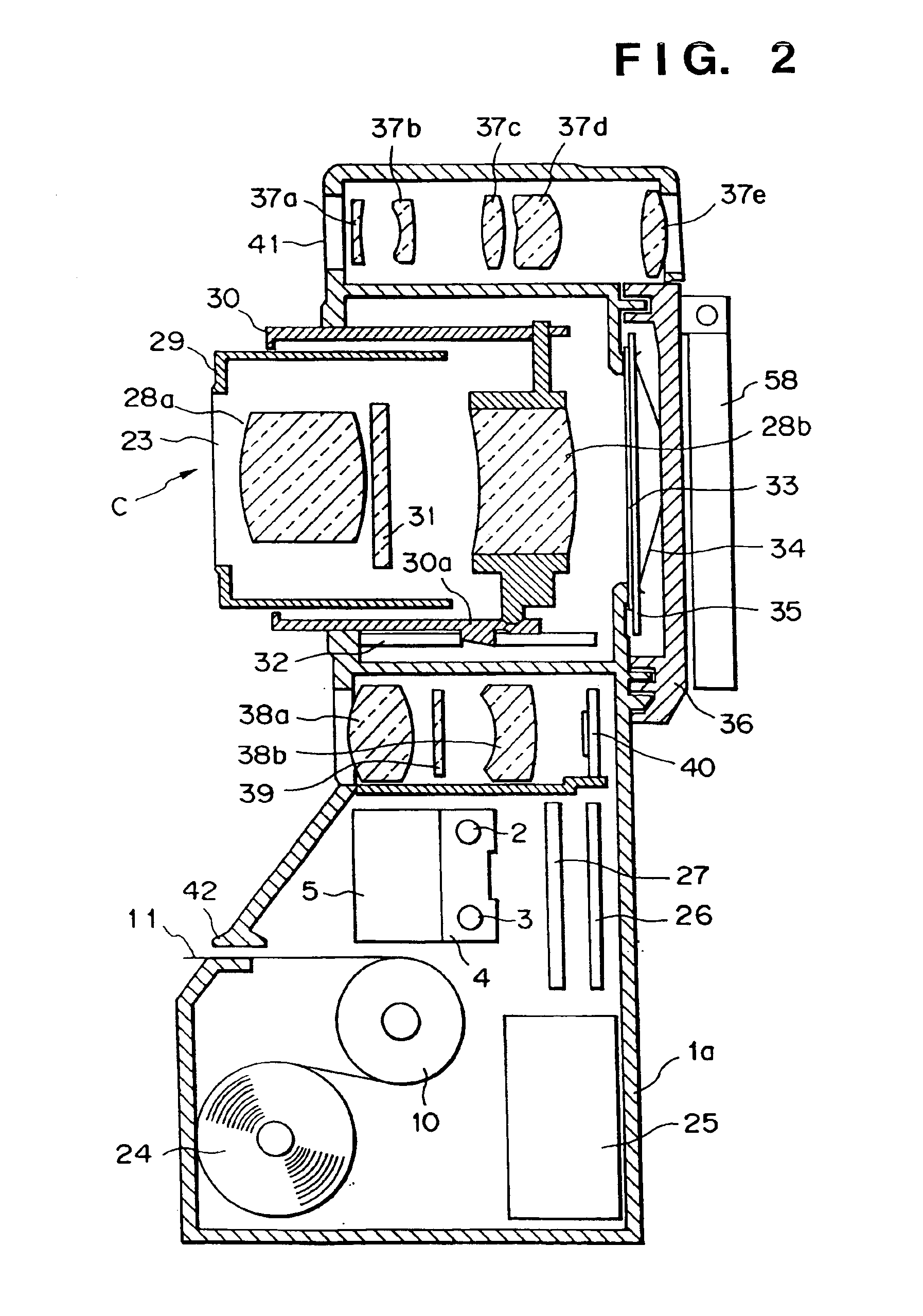
[0042]FIG. 1 is a perspective view showing the external view of a printer-built-in camera according to the first embodiment. FIG. 1 especially shows a structure of an ink-jet printer P. FIG. 2 is a cross-sectional view showing a construction of the printer-built-in camera of the present embodiment. FIG. 3 is a block diagram showing a main construction of the printer-built-in camera of the present embodiment. FIGS. 4 and 5 are flow-charts showing processing in the printer-built-in camera of the present embodiment.

[0043]The camera of this embodiment is a multifunction camera having a still camera C and a printer P which prints an image sensed by the still camera C. The printer P employs an ink-jet printer, and the still camera C employs a camera using a silver chloride film. However, the present invention is not limited to this arrangement but is applicable to other cam...

second embodiment

[Second Embodiment]

[0072]Next, the printer-built-in camera (multifunction camera) according to a second embodiment will be described with reference to FIGS. 7 to 12.

[0073]In the multifunction camera of the second embodiment, the image-sensing device which obtains image information for printing by the printer P is provided on an optical path branched from the image-sensing optical system which forms the image on a silver chloride film. Thus image information can be obtained with approximately the same view angle as that of an image recorded on a silver chloride film.

[0074]More specifically, after the image recorded on the silver chloride film has been developed and print processed, an image with approximately the same view angle as that of an image recorded on the silver chloride film can be print-outputted. Thus the multifunction camera can produce a printout closer to a printout from the silver-chloride film.

[0075]Next, the print operation by the printer P while a capacitor in the ...

third embodiment

[Third Embodiment]

[0101]Next, a third embodiment of the present invention will be described. in this embodiment, when printing is instructed, power supply to the electronic view finder (118) is stopped, thus preventing an increase of electric consumption at the battery 25 (123).

[0102]The processing at this time is shown in the flow-charts of FIGS. 14 and 15. Note that the hardware construction of the multifunction camera of the third embodiment is the same as that of the first or second embodiment except that strobe light emission (S9) is not performed. Therefore the explanation of the construction will be omitted.

[0103]At step S51, when the print button 62 is pressed, the process proceeds to step S52, at which point the carriage 4 is moved to the home position and preparatory discharging is performed (S52). At step S53, the print operation is started. The image information stored in the memory 56 is outputted to the printer engine 52, and printing is performed. Next, at step S54, t...


PUM


Abstract

A printer-built-in image-sensing apparatus including a camera which performs image sensing with film exposure, and a printer which prints an image sensed by the camera. After a shutter button has been pressed and image sensing with strobe light emission has been performed, if printing is instructed by pressing of a print button, then electric charging a capacitor of a strobe circuit is made after the completion of the print operation. Otherwise, the charging of the capacitor is started immediately after the image sensing. In this case, even if printing is instructed during the electric charge, printing is started after completion of the electric charge. Thus, electric consumption upon print operation can be reduced and fluctuation of voltage can be suppressed.

Description

[0001]This is a continuation of prior application Ser. No. 09 / 118,960, filed Jul. 17, 1998 now U.S. Pat. No. 6,552,821, which is a divisional of Ser. No. 08 / 697,492, filed Aug. 26, 1996, issued as U.S. Pat. No. 5,847,836, to which priority under 35 U.S.C. §120 is claimed.BACKGROUND OF THE INVENTION[0002]1. Field of Invention[0003]This invention relates to a printer-built-in image-sensing apparatus which print-outputs a sensed image on a print medium immediately after image sensing and an electric-consumption control method in the image sensing apparatus.[0004]2. Description of Related Art[0005]Conventionally, to meet needs to obtain a printout of sensed image on the spot, so-called instant cameras which enable such printout, have been proposed in U.S. Pat. Nos. 3,709,122, 3,727,529, 4,000,500, 4,249,811, and 4,212,524 and the like. Further, an instant film and the like used in those instant cameras have been proposed in U.S. Pat. No. 3,707,116.[0006]However, the conventional instant...

Claims


Application Information

Patent Timeline
IPC IPC(8): H04N1/21H04N1/00
CPCH04N1/00888H04N5/23241H04N1/2154H04N1/2112H04N1/00885H04N23/50H04N23/651H04N23/63
Inventor SUZUKI, ETSUROU
Owner CANON KK
Why Eureka
Try Eureka