Method and apparatus for measuring transmitting time offset of a base station

a technology of transmitting time offset and radio base station, which is applied in the direction of direction finders, instruments, synchronisation arrangements, etc., can solve the problems of different filter delay characteristics of base stations and delay development, and achieve the effect of increasing the measurement accuracy of offset and increasing the accuracy of location measurement system

Inactive Publication Date: 2005-05-03
HITACHI LTD
View PDF7 Cites 47 Cited by
  • Summary
  • Abstract
  • Description
  • Claims
  • Application Information

AI Technical Summary

Benefits of technology

[0010]The method and the apparatus according to the present invention obtain the estimated values of transmitting time offset from the signals received at multiple locations and select the minimum of the estimated offsets to produce the measured transmitting time offset of the radio base stati...

Problems solved by technology

However, because the transmission antenna and the RF unit are connected by a high-frequency cable, a delay develops when the signal generated by the RF unit is propagated through the cable.
Different filter parts, if used in base stations manufactured at different times, r...

Method used


Image

  • Method and apparatus for measuring transmitting time offset of a base station
  • Method and apparatus for measuring transmitting time offset of a base station
  • Method and apparatus for measuring transmitting time offset of a base station

Examples


first embodiment

[0041]FIG. 4 is a block diagram showing the general configuration of an offset measuring apparatus that measures the transmitting time offset of a base station in the present invention.

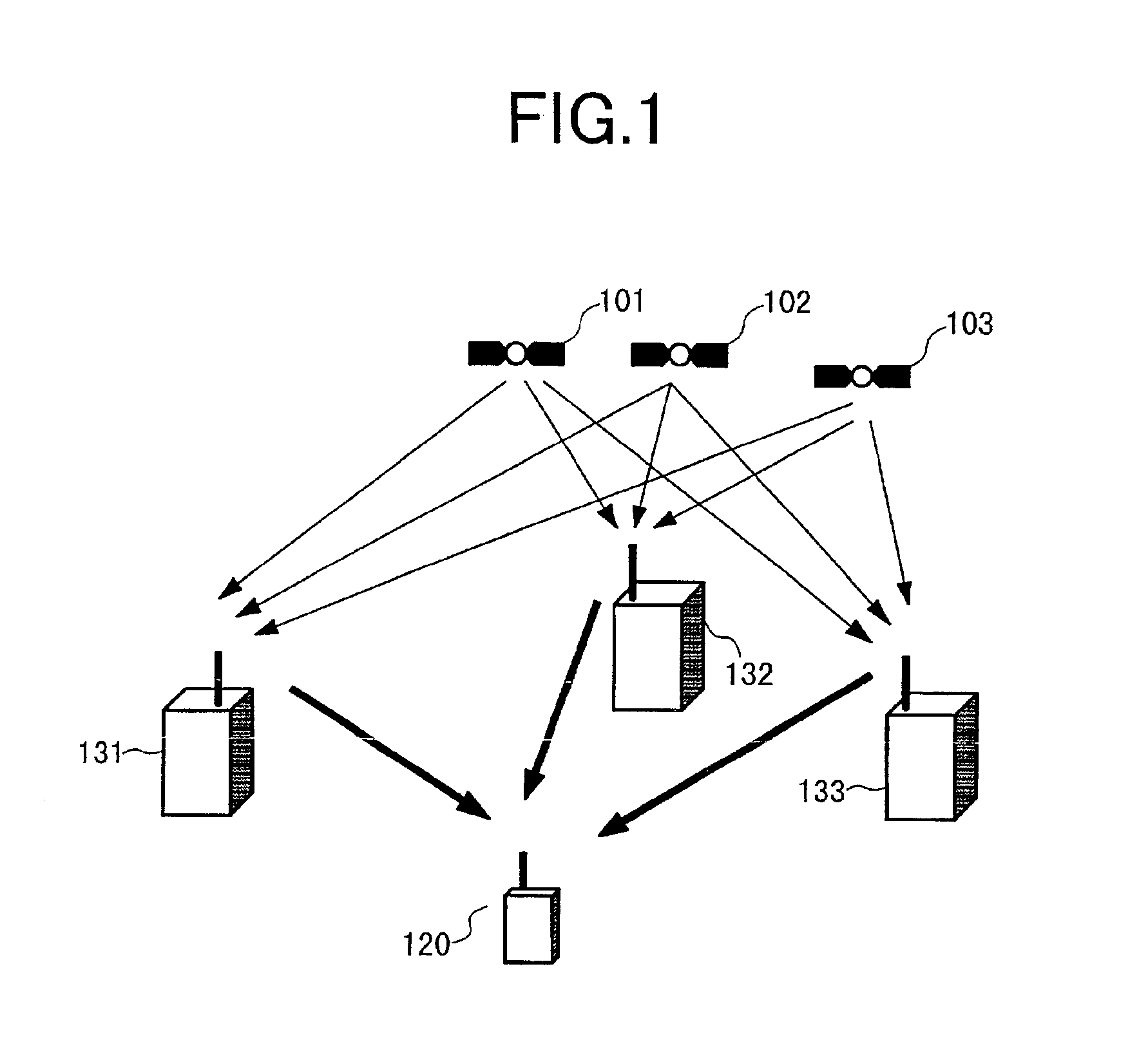
[0042]An offset measuring apparatus 43 comprises an offset determination device 430 and offset estimation devices 431, 432, and 433. Although one offset measuring apparatus 43 has three offset estimation devices 431-433 in the first embodiment, the offset measuring apparatus need not always have three offset estimation devices as long as it has two or more. The offset estimation devices 431, 432, and 433 are installed at separate locations (observation points) for receiving signals from a base station 41 at their own observation points. The observation points where offset estimation devices (431 and so on) are installed need only to be separated one another at least ¼ of the wavelength. This means that, when radio waves are received at locations that are separate one another at least ¼ of the waveleng...

second embodiment

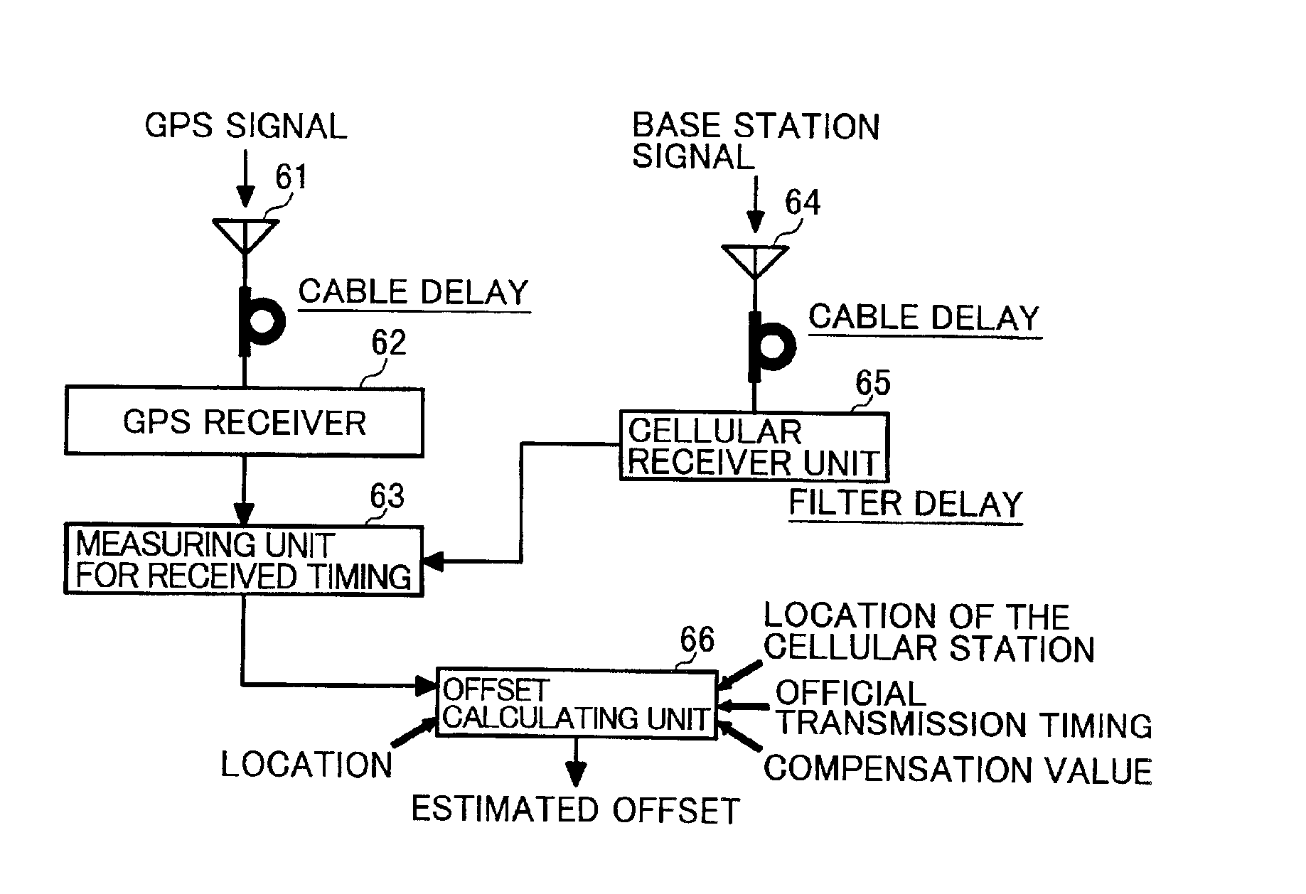
[0079]FIG. 8 is a block diagram showing the general configuration of an offset measuring apparatus in the present invention.

[0080]The offset measuring apparatus in the second embodiment differs from the offset measuring apparatus in the first embodiment described above (FIG. 4, FIG. 6, and FIG. 7) in that one cellular antenna 64 and one cellular receiver unit 85 are provided. The offset measuring apparatus in the second embodiment, which is mounted on a vehicle such as a car when measuring the transmitting time offset of a base station, travels around multiple locations and measures radio waves from the base station to get and store the estimated values of transmitting time offset of the base station at those observation points. After traveling around the multiple observation points for measurement, the device selects the minimum from those stored estimated offsets to produce the measured value of transmitting time offset of the base station.

[0081]Next, the operation of the elements...

third embodiment

[0090]FIG. 9 is a block diagram showing the general configuration of an offset measuring apparatus in the present invention.

[0091]The offset measuring apparatus in the third embodiment differs from the offset measuring apparatus in the first embodiment described above (FIG. 4, FIG. 6, FIG. 7) in that one cellular receiver unit 85 is provided for a plurality of cellular antennas 941, . . . , 94n.

[0092]In the third embodiment, a GPS antenna 61 is connected to a GPS receiver 62. The GPS receiver 62 calculates the location of, and time information (current time of day) on, the offset measuring apparatus from GPS signals received by the antenna 61. The cellular antennas 941, . . . , 94n, extended from an antenna selector 98, are installed at separate locations (observation points) and are connected to the cellular receiver unit 85 via the antenna selector 98.

[0093]The antenna selector 98 selects one of cellular antennas 941, . . . , 94n connected to the cellular receiver unit 85 under i...


PUM


Abstract

An offset measuring method according to the present invention accurately measures a transmitting time offset of a base station. The offset measuring method for receiving signals from the radio base station and measuring the transmitting time offset of the radio base station includes the steps of calculating estimated values of transmitting time offset based on signals received at a plurality of observation points and selecting a minimum from the estimated offsets to determine the selected minimum value as transmitting time offset of the radio base station.

Description

BACKGROUND OF THE INVENTION[0001]The present invention relates to a method for measuring the transmitting time offset of a radio base station.[0002]For use in a mobile communication system, a technology is proposed for detecting the location of a mobile device with the use of signals sent from a base station. For example, JP-A-7-181242 discloses a technology for measuring the location of a mobile device in a Code Division Multiple Access (CDMA) system. This technology measures the location of a mobile device by calculating a time difference between PN code transmission times of the base stations using the location of each base station and the propagation time of signals from each base station to the mobile device.SUMMARY OF THE INVENTION[0003]When measuring the location of a mobile device in a mobile communication system, it is required that the location of the transmission antenna of each base station be identified accurately and that the time (transmitting time or transmission tim...

Claims


Application Information

Patent Timeline
IPC IPC(8): G01S1/00G01S1/02G01S5/02G01S5/10H04Q7/38G01S19/14H04B7/08H04B7/155H04B7/26H04W56/00H04W64/00H04W88/02
CPCG01S5/02G01S19/235G01S5/10G01S5/021G01S5/0244H04W56/00H04W88/08H04B7/155
Inventor OGINO, ATSUSHIKUWAHARA, MIKIOISHIFUJI, TOMOAKIFUJISHIMA, KENZABURO
Owner HITACHI LTD
Why Eureka
Try Eureka