
Work cutting apparatus and method for cutting work

Inactive Publication Date: 2005-05-10
HITACHI METALS LTD
View PDF43 Cites 18 Cited by
  • Summary
  • Abstract
  • Description
  • Claims
  • Application Information

AI Technical Summary

Benefits of technology

[0008]It is therefore a primary object of the present invention to provide a work cutting apparatus and a method for cutting a work capable of improving the cutting accuracy and productivity.

Problems solved by technology

Further, according to the convention, as shown in FIG. 24, a stroke L2 of the cutting blade 3 necessary for the cutting is long, and therefore a long time is required for the cutting operation, posing a problem of poor operability.

Method used


Image

  • Work cutting apparatus and method for cutting work
  • Work cutting apparatus and method for cutting work
  • Work cutting apparatus and method for cutting work

Examples


Embodiment Construction

[0057]Hereinafter, embodiments of the present invention will be described with reference to the attached drawings.

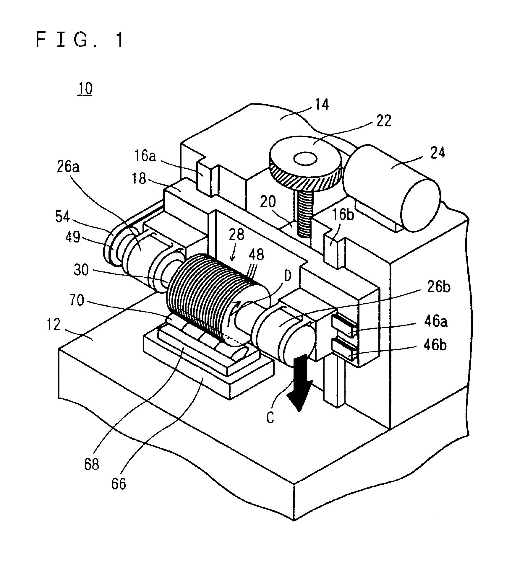
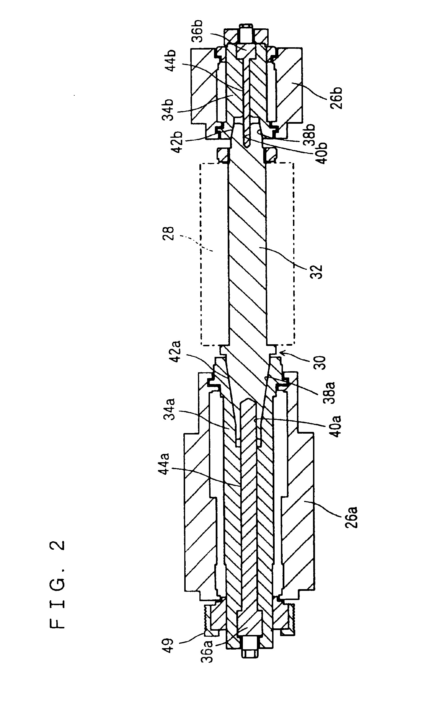
[0058]Referring to FIG. 1, a work cutting apparatus 10 as an embodiment of the present invention is a portal thin-bladed double-end-supported cutting apparatus, and comprises a bed 12. The bed 12 has an upper surface provided with a column 14 having a generally U-shaped cross section. The column 14 has a front surface formed with a pair of rails 16a, 16b parallel to each other, running in the vertical direction. The pair of rails 16a, 16b guide a slider 18 which is slidable in vertical directions (along a Z axis). The slider 18 has a back surface provided with a slider supporting portion 20 formed with a vertical threaded hole. The threaded hole of the slider supporting portion 20 is threaded by a screw 22 serving as a feeding shaft for cutting. The screw 22 is rotated by a lifting motor 24 disposed on the column 14. Therefore, the lifting motor 24 controls turning of th...


PUM

PropertyMeasurementUnit
Pressureaaaaaaaaaa
Lengthaaaaaaaaaa
Lengthaaaaaaaaaa

Abstract

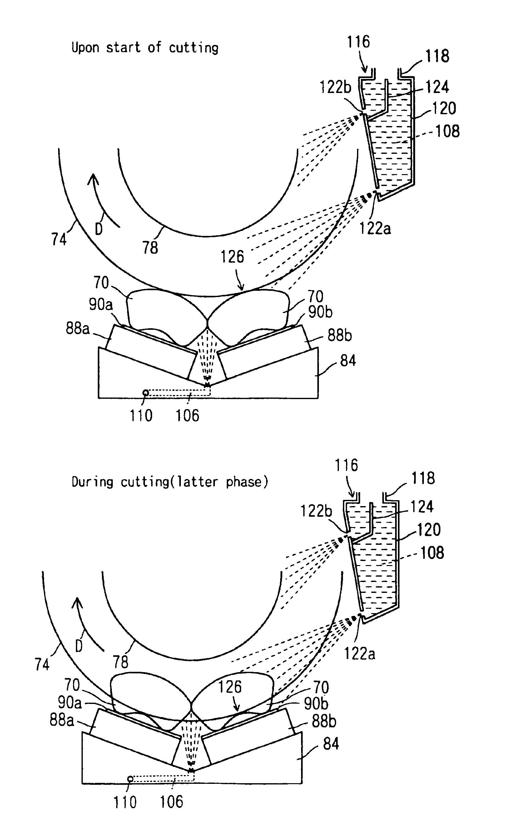
A work cutting apparatus comprises a bed. The bed has an upper surface provided with a column including a rail slidably mounted with a slider. The slider has a front surface mounted with a supporting portion supporting two end portions of a rotating shaft. The rotating shaft is mounted with a plurality of cutting blade blocks. Each of the cutting blade blocks includes a plurality of cutting blades and a thicker cutting blade at each end of the cutting blade block. A table provided with a recess having a V-shaped section is disposed on the bed right beneath the cutting blade blocks. A plurality of works are disposed in the recess, each fixed by a fixing member. The cutting blades lowered while rotating, thereby cutting the works. During this operation, coolant is discharged from a plurality of supplying ports of a coolant supplying portion as well as from a supplying port of a coolant supplying path.

Description

[0001]This application is a Divisional Application of prior application having U.S. Ser. No. 09 / 494,124 filed Jan. 28, 2000 now U.S. Pat. No. 6,595,094.BACKGROUND OF THE INVENTION[0002]1. Field of the Invention[0003]The present invention relates to a work cutting apparatus and a method for cutting a work, and specifically to a work cutting apparatus and a method for cutting a sintered compact such as a magnet.[0004]2. Description of the Related Art[0005]FIG. 22 shows a conventional work cutting apparatus for obtaining a magnet used in a voice coil motor for example. This work cutting apparatus 1 is an overhang model of a so-called cantilever type. A rotating shaft 2 is mounted with a plurality of cutting blades 3 spaced from each other by spacers (not illustrated). The rotating shaft 2 has an end portion supported by a support arm 4. The work cutting apparatus 1 includes an X-slider 6 slidably placed on rails 5. The X-slider 6 has an upper surface provided with a chuck table 7. The ...

Claims


Application Information

Patent Timeline
IPC IPC(8): B28D5/02B28D5/00B27B5/00B27B5/30
CPCB27B5/30B28D5/0076B28D5/029B28D5/023B28D5/0082Y10T83/04Y10T83/263Y10T83/283Y10T83/7688Y10T83/7693Y10T83/778Y10T83/9469
Inventor KONDO, SADAHIKOSASAKI, TOSHIAKICHIKUBA, MASANORIHIYOKE, TOSHIFUMIOZAKI, SAJIO
Owner HITACHI METALS LTD
Learn More