Fuel rail assembly and forming method

a technology of fuel rail and assembly method, which is applied in the direction of liquid fuel feeders, machines/engines, hose connections, etc., can solve the problems of fuel leakage from the connections between the conduits, and achieve the effect of eliminating the cracks in the connecting points

Active Publication Date: 2005-05-10
USUI KOKUSAI SANGYO KAISHA LTD
View PDF15 Cites 19 Cited by
  • Summary
  • Abstract
  • Description
  • Claims
  • Application Information

AI Technical Summary

Benefits of technology

[0006]It is an object of the present invention to provide a fuel rail which can eli

Problems solved by technology

Due to the high pressure of fuel liquid, pressure fluctuations, mechanical vibrations, and dimensional changes

Method used


Image

  • Fuel rail assembly and forming method
  • Fuel rail assembly and forming method
  • Fuel rail assembly and forming method

Examples


Embodiment Construction

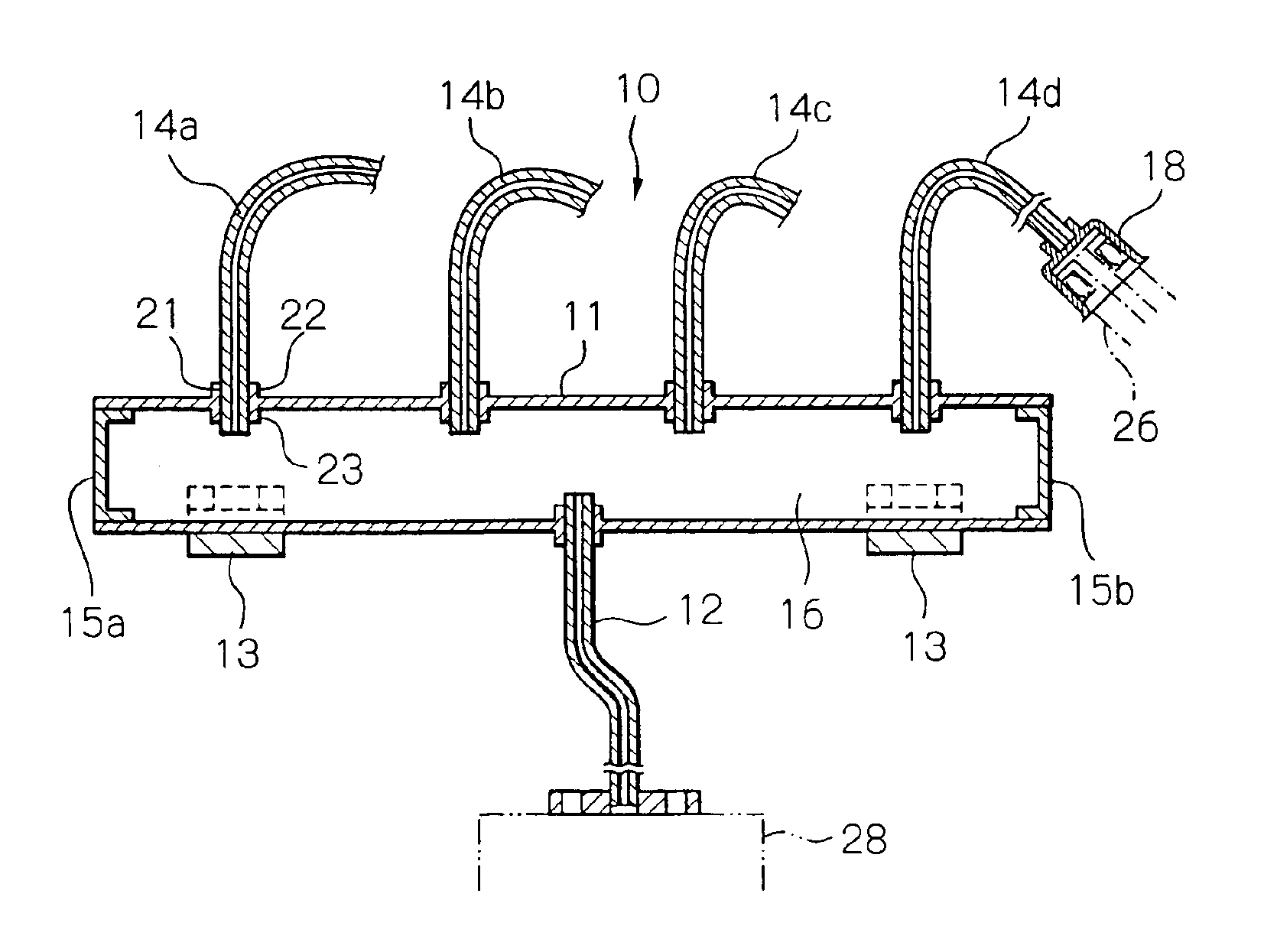
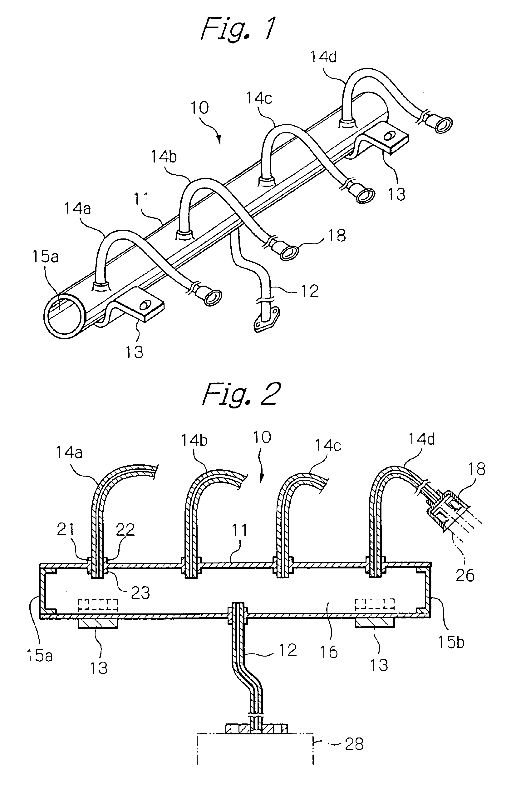
[0036]Referring to FIGS. 1 and 2, there is shown a first type of embodiment of the present invention, a fuel rail assembly 10, which is adapted for use in a low pressure type fuel delivery rail assembly for an automotive four-cylinder engine, especially a low pressure gasoline engine. The fuel rail assembly 10 comprises a fuel rail conduit (main pipe) 11 which has a longitudinal fuel passage 16 therein, a fuel inlet pipe 12 which is fixed to a side of the conduit, and four branch pipes 14a, 14b, 14g, 14d vertically fixed to the conduit.

[0037]The basal end of each branch pipe is adapted to communicate with the fuel passage 16, and the distal end of each branch pipe is provided with a connecting member 18 (socket) for receiving a tip of a fuel injector 26.

[0038]To the bottom of the conduit 11, two thick and rigid brackets 13 are fixed transversely so as to mount the assembly 10 onto the engine body. Longitudinal ends of the conduit 11 are sealed by the end caps 15a, 15b. The basal end...


PUM

PropertyMeasurementUnit
Shapeaaaaaaaaaa

Abstract

A fuel rail assembly for supplying fuel to a plurality of fuel injectors in an engine is provided. This assembly comprises an elongated conduit having a longitudinal fuel passage therein, a fuel inlet pipe fixed to an end or a side of the conduit, and a plurality of branch pipes. The basal end of each branch pipe is adapted to communicate with the fuel passage. The distal end of each branch pipe is provide with a connecting member for connecting to a tip of a fuel injector. The wall of the conduit is provided with holes for receiving the basal ends of the branch pipes. Around each hole an inner collar and an outer collar are integrally formed with the conduit wall, and each branch pipe is fixed to the collars by brazing or welding. The drilling work is performed by a special drilling tool.

Description

BACKGROUND OF THE INVENTION[0001]This invention relates to a fuel rail assembly for an internal combustion engine, especially for an automotive engine, equipped with an electronic fuel injection system. The fuel rail assembly delivers pressurized fuel supplied from a fuel pump toward intake passages or chambers via associated fuel injectors. The assembly is used to simplify installation of the fuel injectors and the fuel supply passages on the engine. This Invention is more particularly related to connecting constructions between the conduit (main pipe) having a fuel passage therein and branch pipes, and to a method of forming them.[0002]Fuel rails are popularly used for electronic fuel injection systems of gasoline engines. The fuel rail delivers pressurized fuel from the conduit through several branch pipes toward a corresponding fuel injector. In diesel engines, the similar fuel rail is called a common rail and is usually designed to withstand extremely high pressure of diesel fu...

Claims


Application Information

Patent Timeline
IPC IPC(8): B21C37/29B21C37/15F02M55/02F02M69/46F02M55/00F16L41/08
CPCF02M55/004F02M55/02F16L41/082F02M69/462F02M69/465F02M55/025
Inventor USUI, MASAYOSHIWATANABE, TOSHIKAZU
Owner USUI KOKUSAI SANGYO KAISHA LTD
Why Eureka
Try Eureka