Source chemical container assembly

a container and chemical technology, applied in the direction of closures, chemical vapor deposition coatings, coatings, etc., can solve the problems of high temperature, harmful to the health of polymer o-rings, and the inability of polymer o-rings to be used to seal the removable closure, etc., to achieve good sealing properties, strong tension chain, and large compressive force

Inactive Publication Date: 2005-05-10
ASM INTERNATIONAL
View PDF8 Cites 393 Cited by
  • Summary
  • Abstract
  • Description
  • Claims
  • Application Information

AI Technical Summary

Benefits of technology

[0012]As outlined above, copper and aluminum are the most frequently used metals for the sealing gaskets. Because of their ductility, these metals show good sealing properties. For the present source chemical container application, it is preferred to use a nickel gasket, nickel alloy gasket, nickel-coated gasket, precious metal (e.g. gold) coated metal gasket or annealed transition meta...

Problems solved by technology

A polymer O-ring typically cannot be used to seal the removable closure against the container because it is not UHV compatible.
Another problem related to the use of polymer O-rings is that polymer O-rings slowly deteriorate in contact with many of the chemicals used in such containers.
Such high temperatures are also harmful to polymer O-rings.
However, the two most widely used metals for metals seals, namely aluminum and copper, a...

Method used


Image

  • Source chemical container assembly
  • Source chemical container assembly
  • Source chemical container assembly

Examples


Embodiment Construction

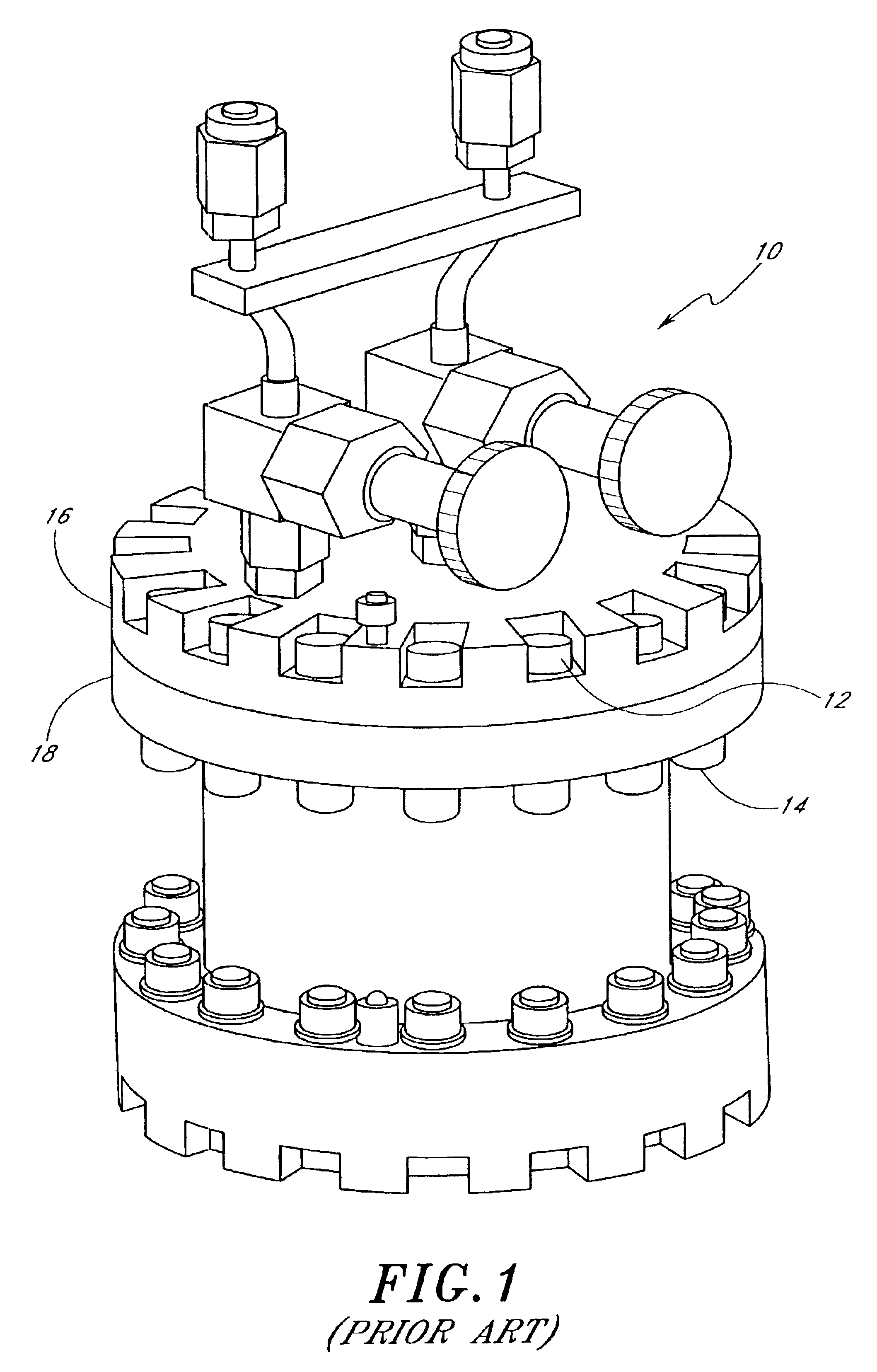
[0019]FIG. 1 illustrates a source chemical assembly 10 according to the prior art. A metal seal (not shown) is applied between two flanges 16, 18, requiring a large number of bolts 14 individually threaded through nuts 12 to be able to apply a sufficiently high force over the whole sealing surface.

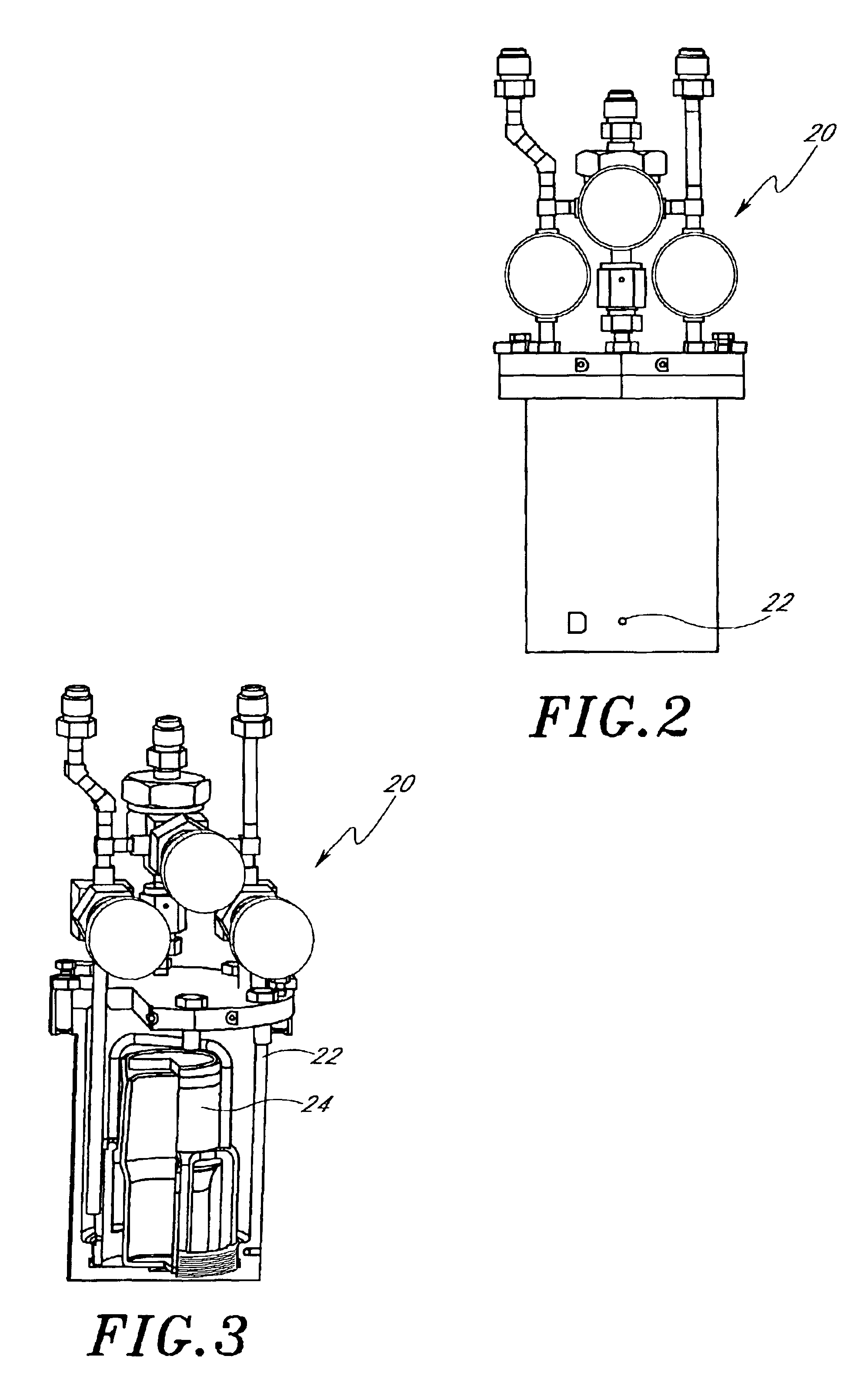
[0020]FIGS. 2 and 3 illustrate an improvement over conventional source chemical containers used in connection with vapor deposition equipment. In particular, a source chemical container 20 includes an outer container 22 and an inner container 24. The inner container 24, shown in the cut-away view of FIG. 3, facilitates loading and unloading of the source chemical. Such a system is disclosed in co-owned Finnish application FI 20001166, filed on May 15, 2000 and corresponding U.S. publication No. 2001 / 0042523, published Nov. 22, 2001 (hereinafter “Kesala”), the disclosure of which is incorporated herein by reference.

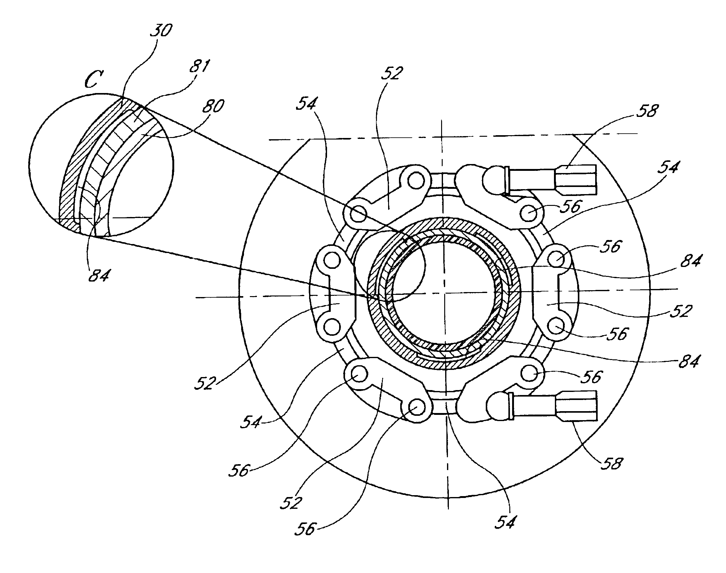
[0021]FIG. 4 indicates a source chemical assembly in accordance with a prefe...


PUM

PropertyMeasurementUnit
Forceaaaaaaaaaa
Circumferenceaaaaaaaaaa
Symmetryaaaaaaaaaa

Abstract

The invention relates to a source chemical container assembly, comprising a metal container functioning as a vacuum chamber and provided with a removable closure, which removable closure seals against the metal container with a metal seal. In order to facilitate easy recharging of the container assembly, compressive force is applied to the metal seal through a tension chain. In a preferred embodiment of the invention the metal seal and the tension chain are provided along a circumference of said metal container. The assembly can comprise an inner container in which the source chemical is contained.

Description

REFERENCE TO RELATED APPLICATION[0001]This application claims the priority benefit under 35 U.S.C. §119(e) to U.S. provisional patent application No. 60 / 302,774, filed Jul. 3, 2001, the disclosure of which is incorporated herein by reference.FIELD OF THE INVENTION[0002]This invention relates to the field of source chemical container assemblies to contain source chemicals to be delivered to a reaction chamber to perform vapor deposition or related processes in the reaction chamber.BACKGROUND OF THE INVENTION[0003]In chemical vapor deposition (CVD) and related vapor deposition techniques, such as atomic layer deposition (ALD), liquid or solid source chemicals are often used. Many of those chemicals react aggressively with moisture and / or oxygen. In order to preserve the purity and volatility of these source chemicals, the container in which they are stored should be vacuum tight to a high degree, compatible with ultra high vacuum (UHV) conditions. It is convenient to use a metal conta...

Claims


Application Information

Patent Timeline
IPC IPC(8): C23C16/448C23C16/44F16L23/10
CPCC23C16/4409F16L23/10C23C16/4481C23C16/448
Inventor LINDFORS, SVENVON ZWEYGBERGK, JANKUKKONEN, MARKO J.
Owner ASM INTERNATIONAL
Why Eureka
Try Eureka