Multi-face forming mask device for vacuum deposition

a mask device and mask technology, applied in vacuum evaporation coatings, electroluminescent light sources, coatings, etc., can solve the problems of reducing productivity, unable to achieve highly accurate patterning, and all the foregoing prior arts, and achieve the effect of easy adjustmen

Inactive Publication Date: 2005-05-10
DAI NIPPON PRINTING CO LTD
View PDF14 Cites 41 Cited by
  • Summary
  • Abstract
  • Description
  • Claims
  • Application Information

AI Technical Summary

Benefits of technology

[0033]Another stretching-and-holding means may have second end parts in longitudinally opposite ends of the base plate. The second mask can be held in a longitudinally stretched state by stretching and fastening the second mask to the opposite second end parts. Preferably, a transverse slit is formed on the inner side of one of the second end parts. Since a part of the end part adjacent to the slit is elastically distortable, the end part can be elastically distorted inward by applying a predetermined force to the end part with a vise or the like in attaching the second mask to the base plate. The tensile force acting on the second mask can be easily adjusted to a desired value by fastening the second mask to the end parts in a predetermined tension with the end part elastically distorted, and then removing the pressure applied to the end part by the vise. The first mask can be formed on the inner side of the slit and a second end part can be formed on the outer side of the slit. Since the first end part and the second end part can be separated by the slit, the distortion of the second end part does not affect the first end part. Therefore, the first mask is not distorted and hence fine patterns can be always formed on the substrate.
[0034]Preferably, longitudinal notches extending toward an end part of the base plate are formed at the opposite ends of the slit, respectively. Since the strength of parts between the notches and the end part of the base plate is lower than that of a part between the slit and the end part of the base plate, i.e., a second end part, parts around the notches are distorted concentratedly and the second end part is displaced maintaining its straightness in distorting the second end part inward and fixing the second mask to the second mask fixing region. Consequently, the second mask as fixed to the second mask fixing region is not distorted.

Problems solved by technology

All the foregoing prior arts have problems.
Particularly, when the slits are very fine, the slits cannot be maintained in a desired accuracy and, consequently, highly accurate patterning cannot be achieved.
Since the prior art metal mask 8 has only the single screen part 8A, only one substrate can be processed by each vacuum evaporation process, which reduces productivity.
The cathode separator method adjusts exposure in photolithography to form partition walls having inclined side walls and hence stable manufacture is difficult.

Method used


Image

  • Multi-face forming mask device for vacuum deposition
  • Multi-face forming mask device for vacuum deposition
  • Multi-face forming mask device for vacuum deposition

Examples


first embodiment

[0054

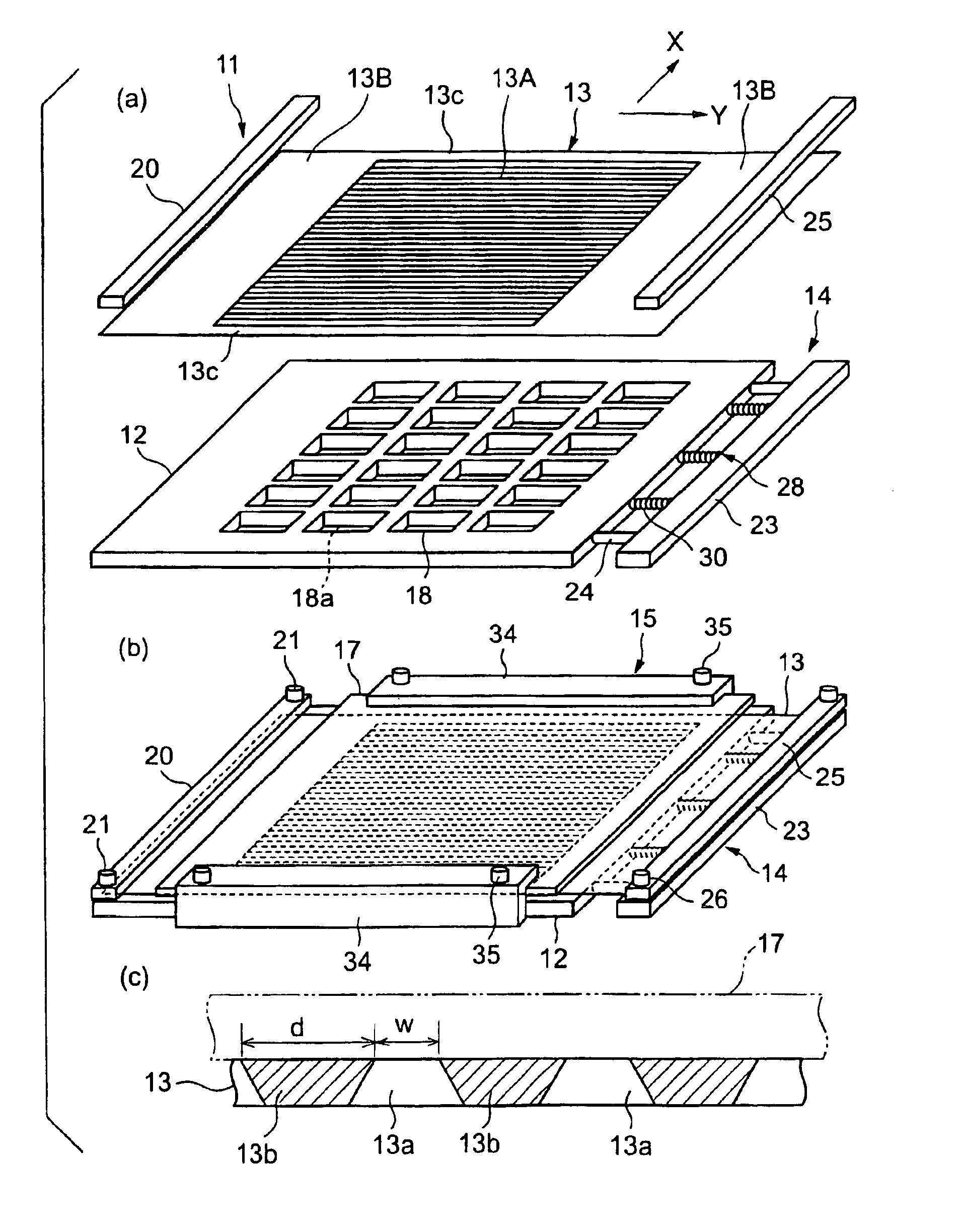
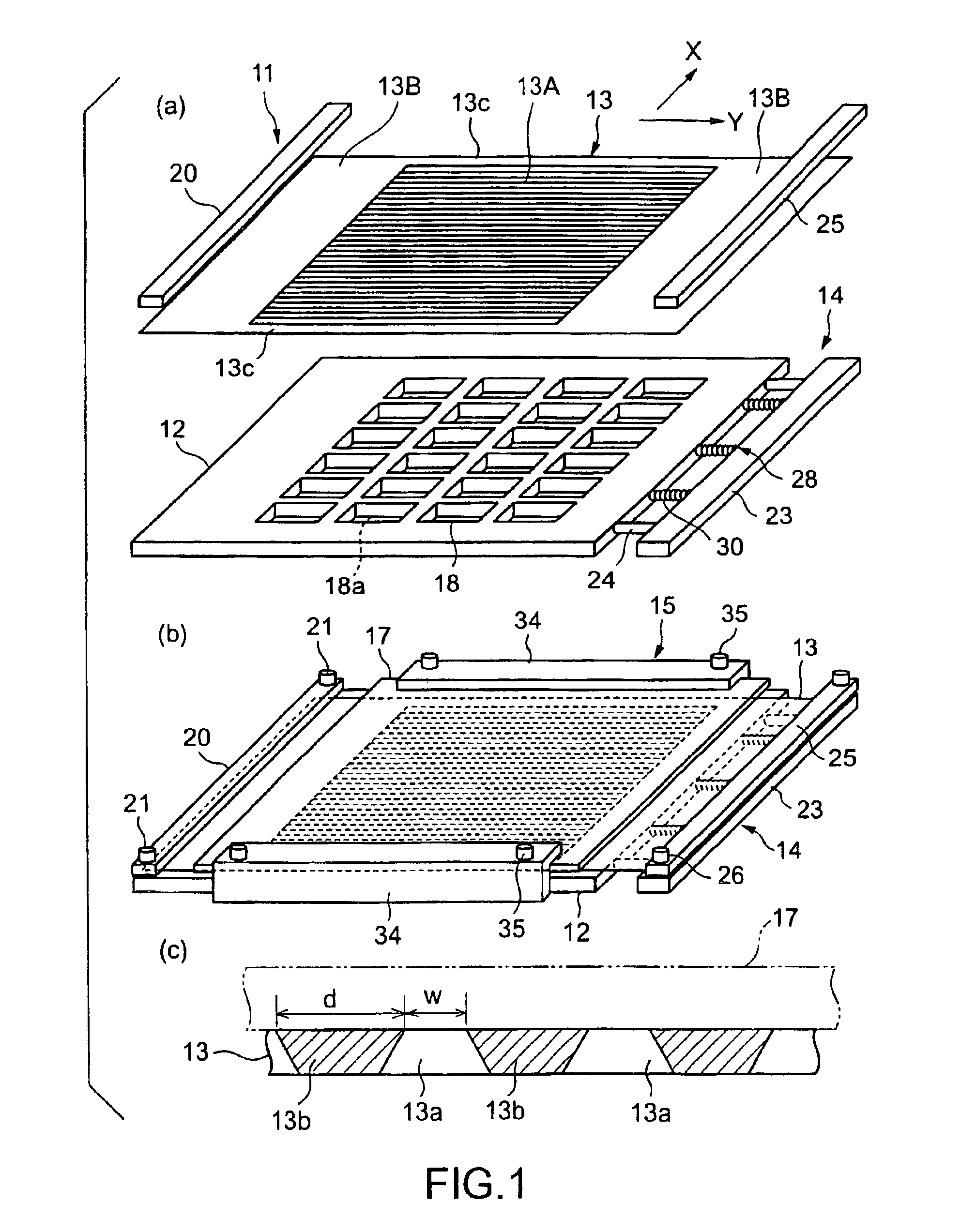
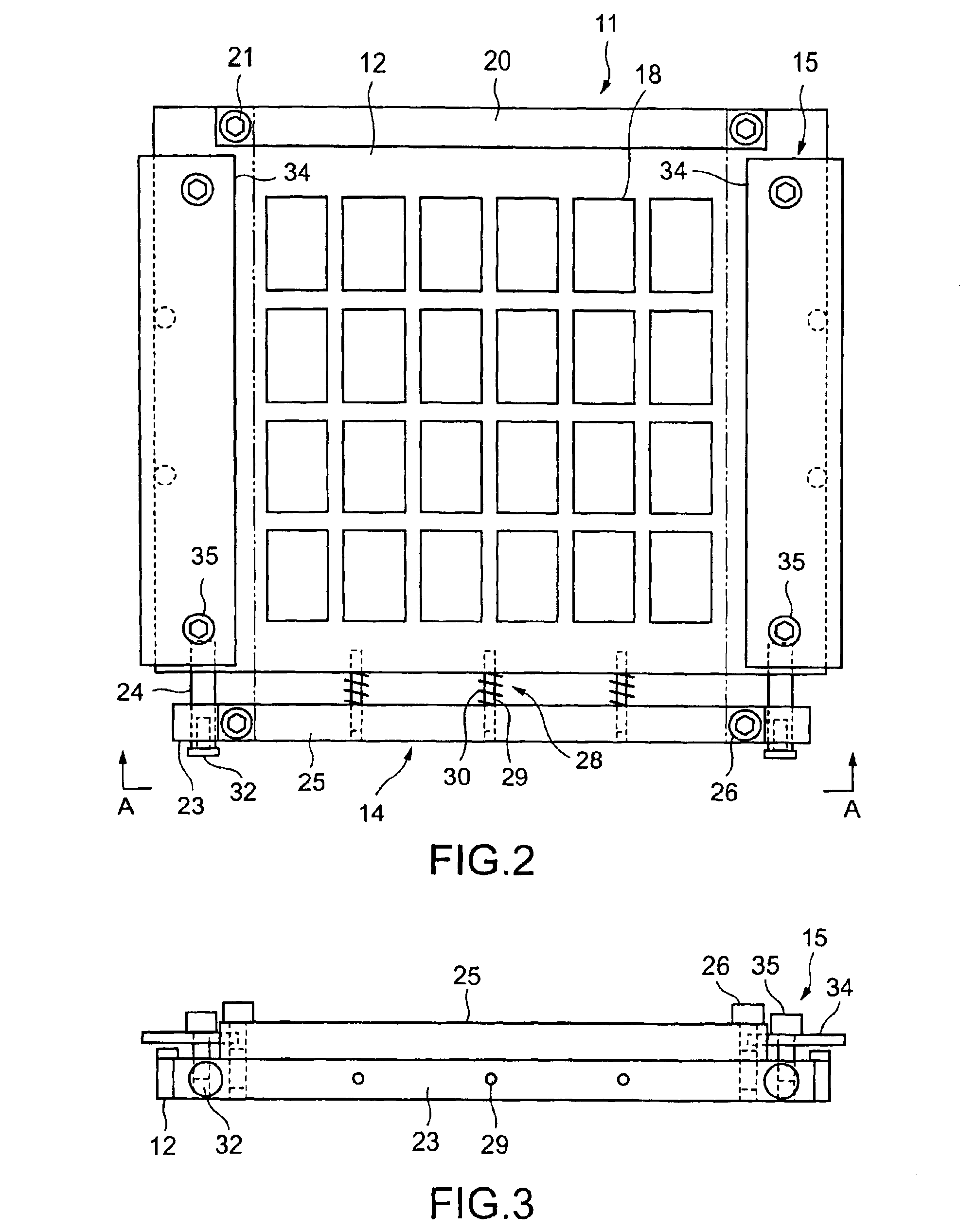
[0055]Preferred embodiments of the present invention will be described with reference to the accompanying drawings. FIG. 1(a) is a schematic, exploded, perspective view of a gang-patterning mask device in a first embodiment according to the present invention for vacuum evaporation to be used in fabricating an organic EL device, showing principal component parts, FIG. 1(b) is a schematic, perspective view of the assembled gang-patterning mask device, FIG. 1(c) is a schematic, fragmentary, enlarged sectional view of a screen part of a second metal mask included in the gang-patterning mask device, FIG. 2 is a schematic plan view of the gang-patterning mask device shown in FIG. 1 with the second metal mask and a base plate removed, FIG. 3 is a schematic end view of the gang-patterning mask device shown in FIG. 2 taken in the direction of the arrows along line A—A in FIG. 2, and FIG. 4 is a schematic plan view of the gang-patterning mask device shown in FIG. 1 with the second metal ...

second embodiment

[0073

[0074]A gang-patterning mask device in a second embodiment according to the present invention will be described with reference to the accompanying drawings. FIG. 7 is a schematic, exploded, perspective view of the gang-patterning mask device in the second embodiment, showing principal component parts, FIGS. 8(a), 8(b) and 8(c) are schematic perspective views of assistance in explaining a mask assembling procedure for assembling the gang-patterning mask device shown in FIG. 7, FIG. 9 is a schematic bottom view taken from the side of a base plate of the assembled gang-patterning mask device shown in FIG. 7, and FIGS. 10(a), 10(b) and 10(c) are a schematic sectional view taken on line A—A in FIG. 9, a schematic sectional view taken on line B—B in FIG. 9, and a sectional view of a part shown in FIG. 10(b) and showing a slit extending outside a mask part, respectively. The gang-patterning mask device generally indicated at 111 comprises, as principal component parts, a base plate 11...


PUM

PropertyMeasurementUnit
lengthaaaaaaaaaa
lengthaaaaaaaaaa
thicknessaaaaaaaaaa

Abstract

A second metal mask (13) having a screen part (13A) provided with a plurality of parallel, fine slits (13a) arranged at very small intervals is placed on a base plate (12) serving also as a first metal mask and provided with a plurality of windows (18) defining regions in which a material is to be deposited. One end of the second metal mask (13) is fastened to the base plate (12) by a mask clamp (20) and the other end of the same is fastened to a slider (23). Resilient force is applied to the slider (23) by compression coil springs (30). Thus, the screen part (13A) of the second metal mask (13) is tensioned and thereby the slits (13a) are stretched straight and are extended at predetermined pitches. A substrate (17) placed on the second mask (13) is subjected to a vacuum evaporation process to form fine patterns on the substrate (17) in a gang-patterning mode.

Description

TECHNICAL FIELD[0001]The present invention relates to a gang-patterning mask device for vacuum evaporation to be used in a vacuum evaporation process for forming a predetermined pattern on a surface of a substrate to fabricate an organic EL device.BACKGROUND ART[0002]Referring to FIG. 17, an organic EL device is formed by forming anodes 2 of ITO, a hole-carrying layer 3, an organic layer (light-emitting layer) 4, an electron-carrying layer 5 and cathodes 6 in that order on a surface of a transparent substrate 1, such as a glass plate. The organic layer 4 is of a high-molecular type or a low-molecular type. Some organic EL devices are of a passive driving system and others are of an active driving system. The low-molecular organic layers of organic EL devices of a passive driving type and those of an active driving type, and the cathodes 6 of the organic EL devices of a passive driving system are formed by vacuum evaporation. A metal mask 8 as shown in FIG. 18 is used in forming the ...

Claims


Application Information

Patent Timeline
Patent Type & Authority Patents(United States)
IPC IPC(8): C23C14/04
CPCC23C14/042H05B33/10
Inventor TSUCHIYA, TERUNAOSAKATA, TAKUYA
Owner DAI NIPPON PRINTING CO LTD
Why Eureka
Try Eureka