
Filter layer for a display, a method of preparing a filter layer for a display and a display including a filter layer

a filter layer and display technology, applied in the field of filter layer for displays, can solve the problems of affecting the display contrast, the method typically needs additional equipment and a manufacturing process modification, and the contrast of the crt generally does not improve significantly. to achieve the effect of improving the contrast of the display

Inactive Publication Date: 2005-05-10
SAMSUNG SDI CO LTD
View PDF25 Cites 16 Cited by
  • Summary
  • Abstract
  • Description
  • Claims
  • Application Information

AI Technical Summary

Benefits of technology

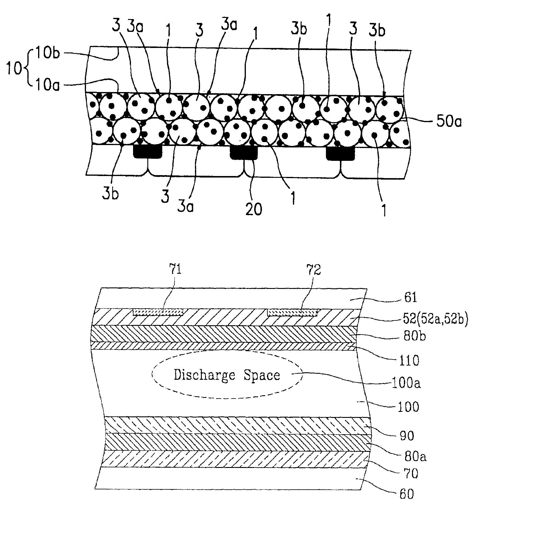
[0016]An objective of the present invention is to provide a filter layer to improve the contrast of a display by absorbing light in the overlapping wavelengths among red (R), green (G) and blue (B) phosphors.

Problems solved by technology

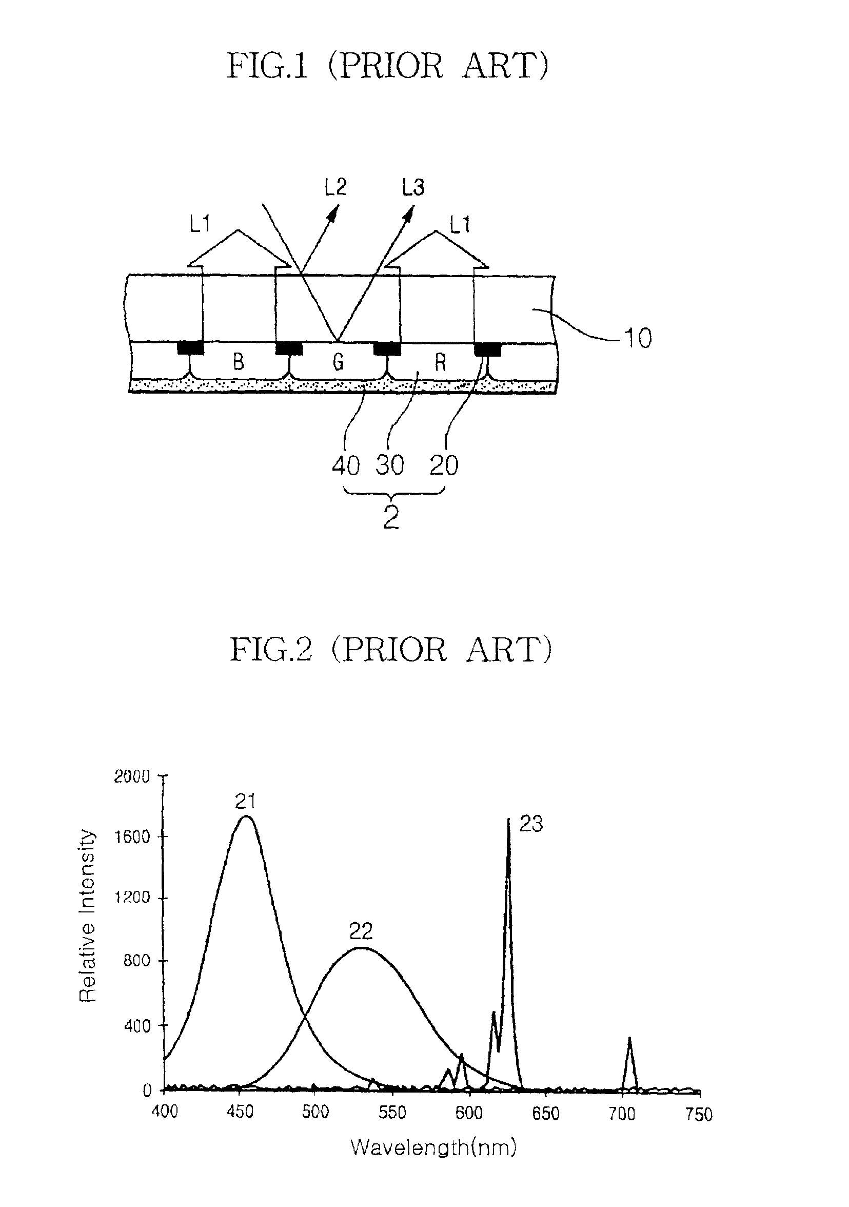
While such a technique can be advantageous with respect to the application of a manufacturing process of a CRT, the dyes and pigments used in the intermediate layer typically have a broad absorption wavelength and, thus, the contrast of the CRT generally does not improve significantly.
However, this method typically needs additional equipment and a modification of the manufacturing process, since coating, light exposing and developing processes for the corresponding filter layer are typically further conducted compared to a conventional technique.

Method used


Image

  • Filter layer for a display, a method of preparing a filter layer for a display and a display including a filter layer
  • Filter layer for a display, a method of preparing a filter layer for a display and a display including a filter layer
  • Filter layer for a display, a method of preparing a filter layer for a display and a display including a filter layer

Examples


example 1

[0095]3.9 grams (g) of Al2O3 dispersed in water and 0.78 g of TiO2 dispersed in water were mixed to prepare a solution including with Al2O3 / TiO2 in a mole ratio of 2 / 10. 15.32 g of water were added to the solution to prepare Al2O3 / TiO2 water-based sol. 0.2 g of HAuCl4, 0.025 g of hydrazine, and 0.05 g of polyvinylbutyral were added to 14.57 g of ethanol, agitated and dissolved to prepare a gold colloid solution. 1.60 g of the gold colloid solution were added to the Al2O3 / TiO2 water-based sol to obtain the resultant coating solution with 0.035 mole % of gold on the basis of the oxide Al2O3 / TiO2.

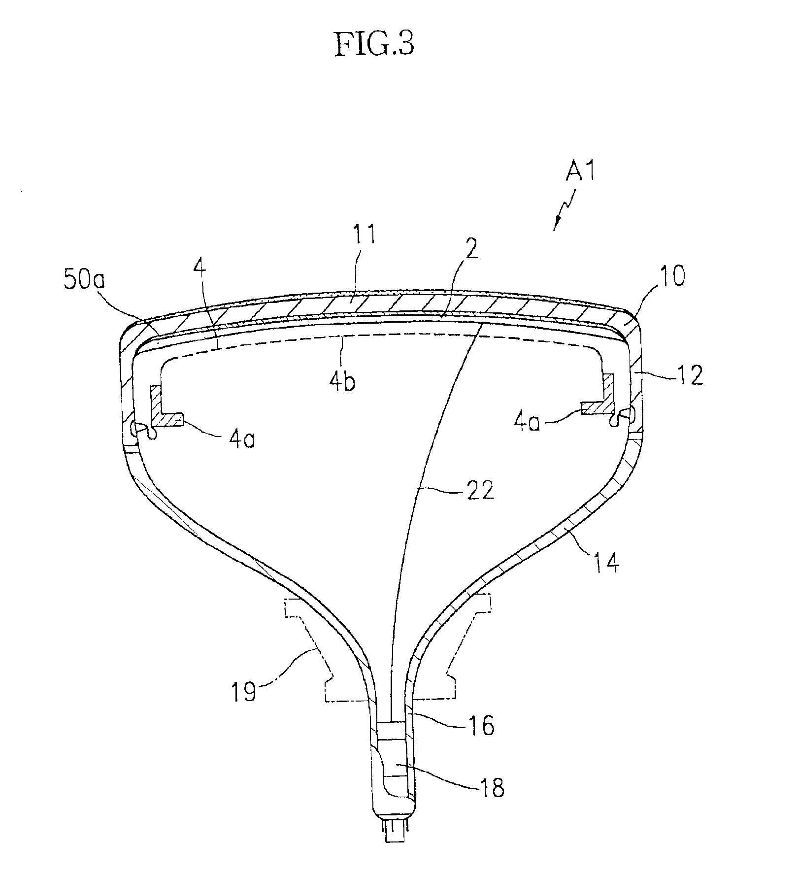
[0096]A black matrix layer was formed on a 17-inch CRT face panel, and 20 ml of the coating solution was spin-coated on the face panel while the face panel was spinning at 150 revolutions per minute (rpm). The coated panel was dried at room temperature to form a filter layer. Next, a phosphor layer was formed on the panel in a conventional way. The thus-made panel is illustrated by the embodim...

example 2

[0097]A CRT face panel was prepared in the same manner as described in Example 1, except that the content of the gold was 0.001 mole % on the basis of the oxide Al2O3 / TiO2.

example 3

[0098]A CRT face panel was prepared in the same manner as described in Example 1, except that the content of the gold was 0.2 mole % on the basis of the oxide Al2O3 / TiO2.


PUM


Abstract

A filter layer for a display and a method of preparing the filter layer, and a display including the filter layer, are provided. The filter layer for a display includes oxide particles and nano-sized metal particulates adhered to the surface of the oxide particles. A surface plasma resonance (SPR) phenomenon is triggered at the interface of the oxide / metal to selectively absorb light of at least one predetermined wavelength.

Description

CLAIM OF PRIORITY[0001]This application makes reference to, incorporates the same herein, and claims all benefits accruing under 35 U.S.C. §119 from our application A FILTER FOR A DISPLAY, A METHOD FOR PREPARING THE SAME AND A DISPLAY COMPRISING THE SAME filed with the Korean Industrial Property Office on 6 Feb. 2001 and there duly assigned Ser. No. 5718 / 2001.BACKGROUND OF THE INVENTION[0002]1. Field of the Invention[0003]The present invention is related to a filter layer for displays, a method of preparing the same and displays including the same and, more particularly, to a light absorbing filter layer for improving contrast and color coordinate ranges of displays, a method of preparing the same and displays including the same.[0004]2. Description of the Related Art[0005]A cathode ray tube (further referred to as CRT) is one of the present major image displays. As large display and high-resolution televisions are in demand, a light and thin flat panel display (FPD) with improved b...

Claims


Application Information

Patent Timeline
Patent Type & Authority Patents(United States)
IPC IPC(8): H01J29/18H01J29/89G09F9/00G09F9/30G02B5/22H01J9/20H01J11/12H01J11/24H01J11/26H01J11/44H01J29/28H01J29/32H01J29/88
CPCH01J29/185H01J29/89H01J29/327H01J2229/8916H01J11/44H01J9/24
Inventor LEE, JONG-HYUKCHO, YOON-HYUNGLEE, HAE-SEUNGZANG, DONG-SIKPARK, JUNG-HWAN
Owner SAMSUNG SDI CO LTD
Learn More