Mechanically flexible organic electroluminescent device with directional light emission

Inactive Publication Date: 2005-05-10
BOE TECH GRP CO LTD
View PDF17 Cites 80 Cited by
  • Summary
  • Abstract
  • Description
  • Claims
  • Application Information

AI Technical Summary

Benefits of technology

[0008]The present invention provides a flexible light-emitting device that has improved external quantum efficiency by channeling substantially all emitted radiation in the forward half space. The term “forward” means in the direction of an observer. The light-emitting device of the present invention also is less susceptible to degradation due to environmental elements compared to prior art OELDs. A flexible light-emitting device of the present invention comprises: (a) a flexible substantially transparent s

Problems solved by technology

Inorganic EL devices, however, typically suffer from a required high activation voltage and low brightness.
Conventional OELDs are built on glass substrates because of low permeability of glass to oxygen and water vapor, which can lead to corrosion or other degradation of the devices.
However, glass substrates are not suitable for certain applications in which flexibility is desired.
In addition, manufacturing pro

Method used


Image

  • Mechanically flexible organic electroluminescent device with directional light emission
  • Mechanically flexible organic electroluminescent device with directional light emission
  • Mechanically flexible organic electroluminescent device with directional light emission

Examples


Embodiment Construction

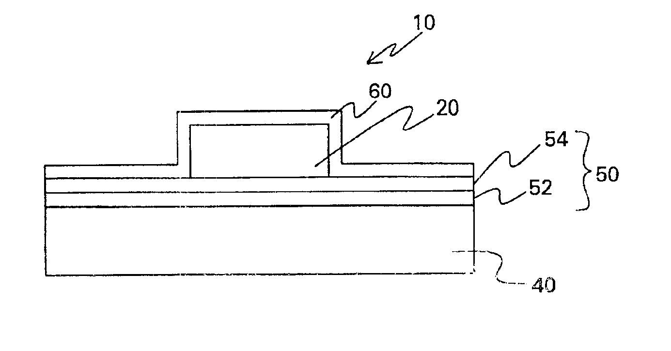
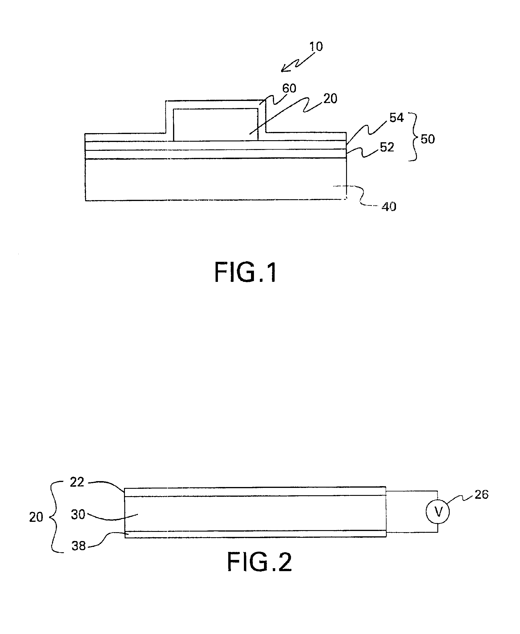
[0025]The present invention provides a flexible light-emitting device that has improved external quantum efficiency by channeling a major portion of the radiation emitted by the OELD in the forward half space. In one aspect of the present invention, the flexible light-emitting device has a large area. Such a light-emitting device can comprise one or more OELDs.

[0026]As used herein, the term “external quantum efficiency” means the ratio of the radiation energy emitted from the OELD to the electrical energy input into the device. The term “flexible” means being capable of being bent into a shape having a radius of curvature of less than about 100 cm. The term “large-area” means having a dimension of an area greater than or equal to about 10 cm2. The term “substantially transparent” means allowing a total transmission of at least about 50 percent, preferably at least about 80 percent, and more preferably at least 90 percent, of light in the visible range (i.e., having wavelength in the...


PUM


Abstract

A mechanically flexible and environmentally stable organic electroluminescent (“EL”) device with directional light emission comprises an organic EL member disposed on a flexible substrate, a surface of which is coated with a multilayer barrier coating which includes at least one sublayer of a substantially transparent organic polymer and at least one sublayer of a substantially transparent inorganic material. The device includes a reflective metal layer disposed on the organic EL member opposite to the substrate. The reflective metal layer provides an increased external quantum efficiency of the device. The reflective metal layer and the multilayer barrier coating form a seal around the organic EL member to reduce the degradation of the device due to environmental elements.

Description

[0001]This invention was first conceived or reduced to practice in the performance of work under contract DE-FC26-00NT40989 awarded by the United States Department of Energy. The United States of America may have certain rights to this invention.BACKGROUND OF THE INVENTION[0002]The present invention relates generally to light-emitting devices having organic electroluminescent material and, more particularly, to light-emitting devices that are environmentally stable and have improved external quantum efficiency.[0003]Electroluminescent (“EL”) devices, which may be classified as either organic or inorganic, are well known in graphic display and imaging art. EL devices have been produced in different shapes for many applications. Inorganic EL devices, however, typically suffer from a required high activation voltage and low brightness. On the other hand, organic EL devices (“OELDs”), which have been developed more recently, offer the benefits of lower activation voltage and higher brig...

Claims


Application Information

Patent Timeline
IPC IPC(8): H01L51/52H01L51/50H05B33/04H05B33/02H05B33/10H05B33/26
CPCH01L51/5237H01L51/5271H01L51/5268H01L2251/5338H10K50/8445H10K50/844H10K50/854H10K50/856H10K2102/311H05B33/00H05B33/22H05B33/04
Inventor DUGGAL, ANIL RAJSHIANG, JOSEPH JOHNSCHAEPKENS, MARC
Owner BOE TECH GRP CO LTD
Why Eureka
Try Eureka