Sensing an object with a plurality of conductors

a technology of conductors and objects, applied in the field of sensing objects with a plurality of conductors, can solve the problems of inconvenient mass production, cumbersome, undesirable, etc., and achieve the effects of reducing power driving requirements, improving response time to a finger or a stylus movement, and reducing the amount of time left for digital and other processing

Inactive Publication Date: 2005-05-10
SENTELIC HLDG CO LTD
View PDF23 Cites 46 Cited by
  • Summary
  • Abstract
  • Description
  • Claims
  • Application Information

AI Technical Summary

Benefits of technology

[0014]In some embodiments of the invention, the processing time overlap allows the conductors to be processed faster than in the sequential systems. The response time to a movement of a finger or a stylus is improved, and / or more time is left for digital and other processing. Also, less circuitry is required than in the simultaneous processing systems. In particular, less analog circuitry is needed, relaxing the analog circuit design and process trimming requirements. In addition, the power driving requirements are reduced compared to the simultaneous processing systems. One embodiment is illustrated in FIG. 8 showing a voltage of a conductor Xn as a function of time. The conductor processing includes a discharge phase Dn, a charging phase Cn, and a sensing phase Sn. In phase Dn, the conductor is discharged to ground. Next, in phase Cn, a predetermined amount of charge is injected into the conductor. Then, in phase Sn, the charge on the conductor is sampled with a sample and hold circuit (not shown). The phases Dn, Cn, Sn are of equal duration. FIG. 9 shows the relative timing of the three phases for the conductors X1, X2, X3. The processing of a conductor is delayed by one phase duration relative to the previous conductor, so that D2 coincides with C1, D3 with C2 and S1, and so on. More generally, the phases Sn, Cn+1, Dn+2 coincide. In each phase period T, at most one conductor is in any given phase (discharge, charge, or sense), so the circuitry for each phase can be shared by different conductors. For example, only one sample and hold circuit is needed. In addition, the current drive requirements for the charging and discharging circuitry (phases Cn and Dn) can be reduced since at most one conductor is charged and at most one conductor is discharged at any time.
[0015]In some embodiments, in each phase period T, one conductor is in the sensing phase S, one conductor is in the charging phase C, and the remaining conductors are in the discharge phase. Advantageously, the grounded conductors (the conductors in the discharge phase) reduce the amount of noise injected into the adjacent conductors.

Problems solved by technology

The simultaneous processing system of FIG. 4 requires much circuitry.
This is particularly undesirable if the analog circuitry (such as the integrators 410) and the digital circuitry are combined on one chip.
Manufacturing the analog circuitry with a standard digital circuit process may require a precise analog circuit design or process trimming, which is cumbersome and inefficient for mass production.
On the other hand, the sequential processing systems are slower.

Method used


Image

  • Sensing an object with a plurality of conductors
  • Sensing an object with a plurality of conductors
  • Sensing an object with a plurality of conductors

Examples


Embodiment Construction

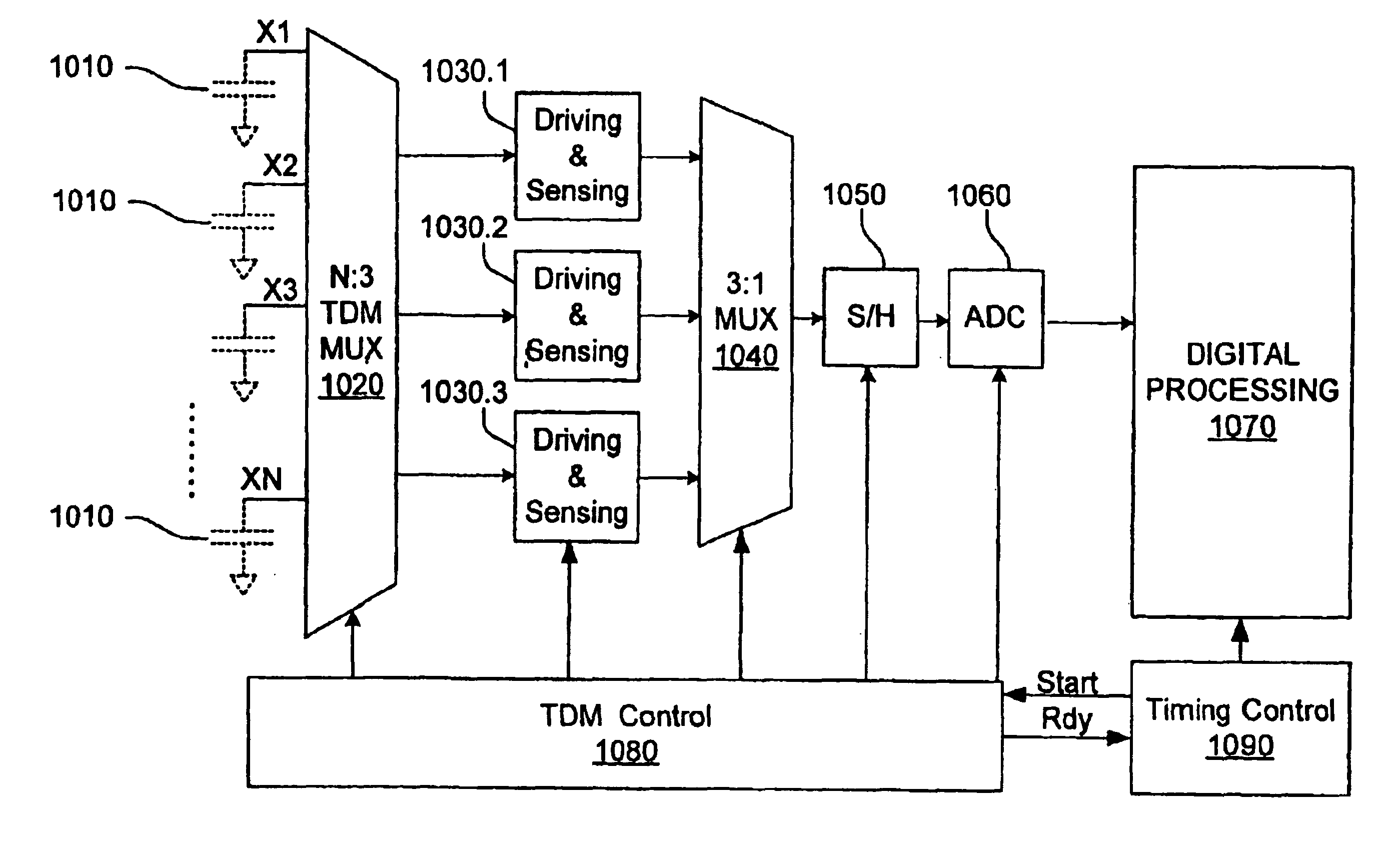
[0033]FIG. 10 illustrates an example touch sensitive system that implements the timing of FIGS. 8 and 9. Capacitors 1010 schematically represent the capacitances of the respective conductors X1 . . . XN. The capacitors are not actually present in the circuit. The total capacitance of a conductor, as represented by a capacitor 1010, includes a base capacitance (e.g. the capacitance associated with the position of the conductors on a touch pad substrate, which can be a printed circuit board) and a capacitance due to a proximity of a conductive object such as a finger or a stylus.

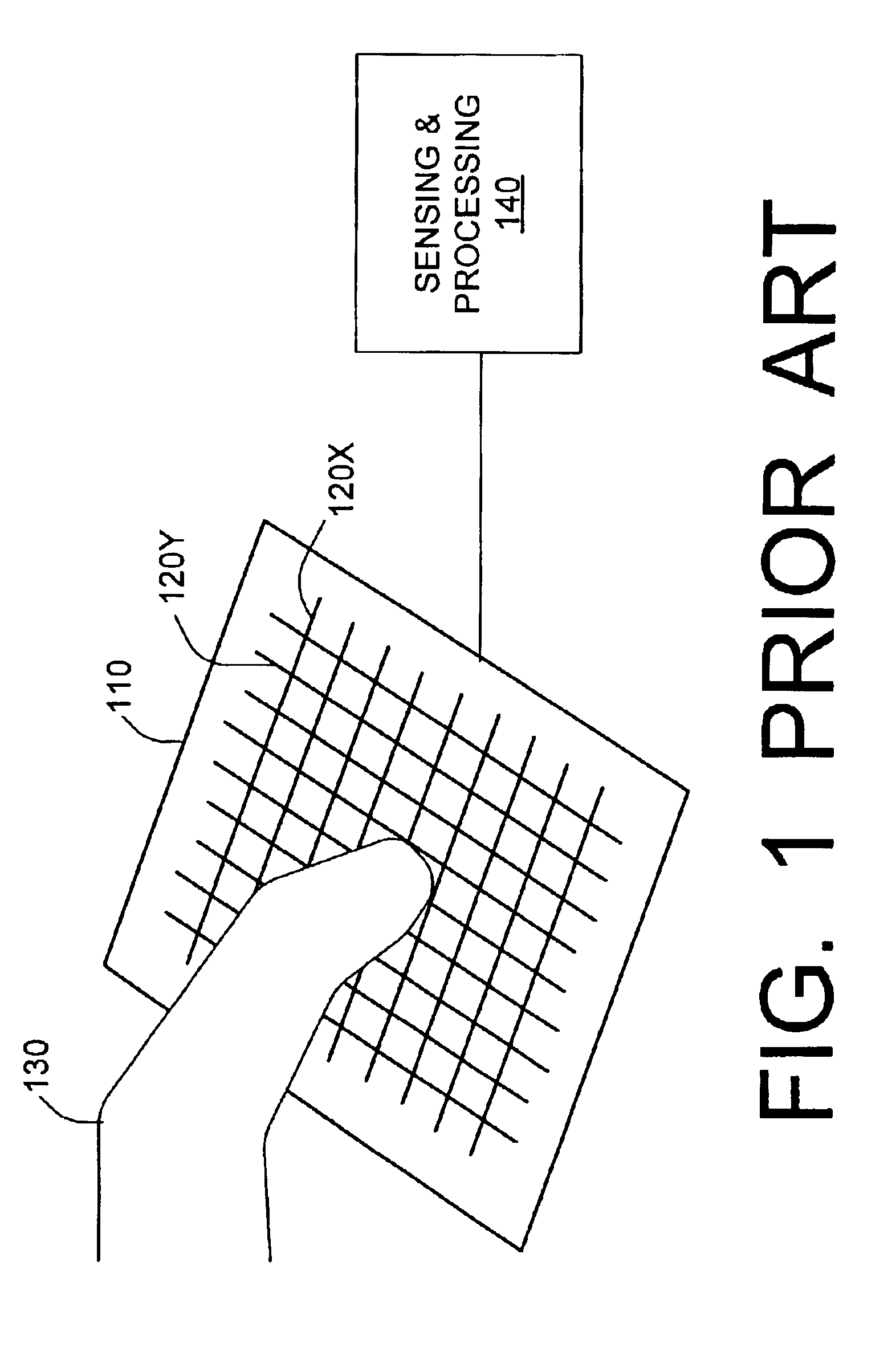
[0034]The conductors can be arranged as in FIG. 1 or in any other suitable fashion. For example, a radial arrangement is possible as in the aforementioned U.S. Pat. No. 4,736,191, incorporated herein by reference. The conductors can be arranged on a flat or curved surface or in any suitable way.

[0035]The N conductors are connected to inputs of N:3 multiplexer 1020. In each phase period T (FIG. 9), multiplexer ...


PUM


Abstract

An object (130), e.g. a human finger or a stylus, is sensed with a plurality of conductors (120, X1, . . . XN). The conductor processing times (TX1, TX2, . . . TXN) but are shifted relative to one other.

Description

BACKGROUND OF THE INVENTION[0001]The present invention relates to sensing an object with a plurality of conductors. Some embodiments relate to touch sensitive pads that sense a human finger or a stylus.[0002]Touch sensitive pads are used in computers, microwave ovens, and other devices. A touch sensitive pad allows a user (a human being) to enter information by touching the pad with a finger or a stylus. In computer systems, touch sensitive pads provide a compact alternative to a mouse, and are used extensively in laptop and notebook computers. Some systems allow the user to enter verbal information into a computer by writing the information on a touch sensitive pad. Some devices do not require the user to touch the pad, it is sufficient for the user to place the object (the finger or the stylus) close to the pad. We will still call these pads “touch sensitive” herein.[0003]FIG. 1 illustrates an exemplary system with a touch sensitive pad 110. The pad has a number of conductors 120X...

Claims


Application Information

Patent Timeline
Patent Type & Authority Patents(United States)
IPC IPC(8): G06F3/033G06F3/044G06F3/0354G06F3/041H01H13/00H01H36/00
CPCG06F3/044G06F3/04166G06F3/0446
Inventor LIN, JAOCHING
Owner SENTELIC HLDG CO LTD
Why Eureka
Try Eureka